Infusion assembly for beverage preparing machine

a technology of infusion assembly and beverage preparation machine, which is applied in beverage vessels, domestic applications, kitchen equipment, etc., to achieve the effect of improving the general compactness and lateral dimensions of the infusion assembly

Active Publication Date: 2009-10-08
PERFECT STEAM APPLIANCE
View PDF6 Cites 68 Cited by
  • Summary
  • Abstract
  • Description
  • Claims
  • Application Information

AI Technical Summary

Benefits of technology

[0014]The aim of the present invention is to provide an infusion assembly particularly for machines for preparing beverages in which both the lateral dimensions and the general compactness of the infusion assembly are improved with respect to known types of infusion assemblies.
[0016]Another object of the present invention is to provide an infusion assembly particularly for machines for preparing beverages which is highly reliable, relatively simple to provide and at competitive costs.

Problems solved by technology

There are also infusion assemblies in which the arms that hold the capsule are external, with problems as regards space occupation.

Method used


Image

  • Infusion assembly for beverage preparing machine
  • Infusion assembly for beverage preparing machine
  • Infusion assembly for beverage preparing machine

Examples


first embodiment

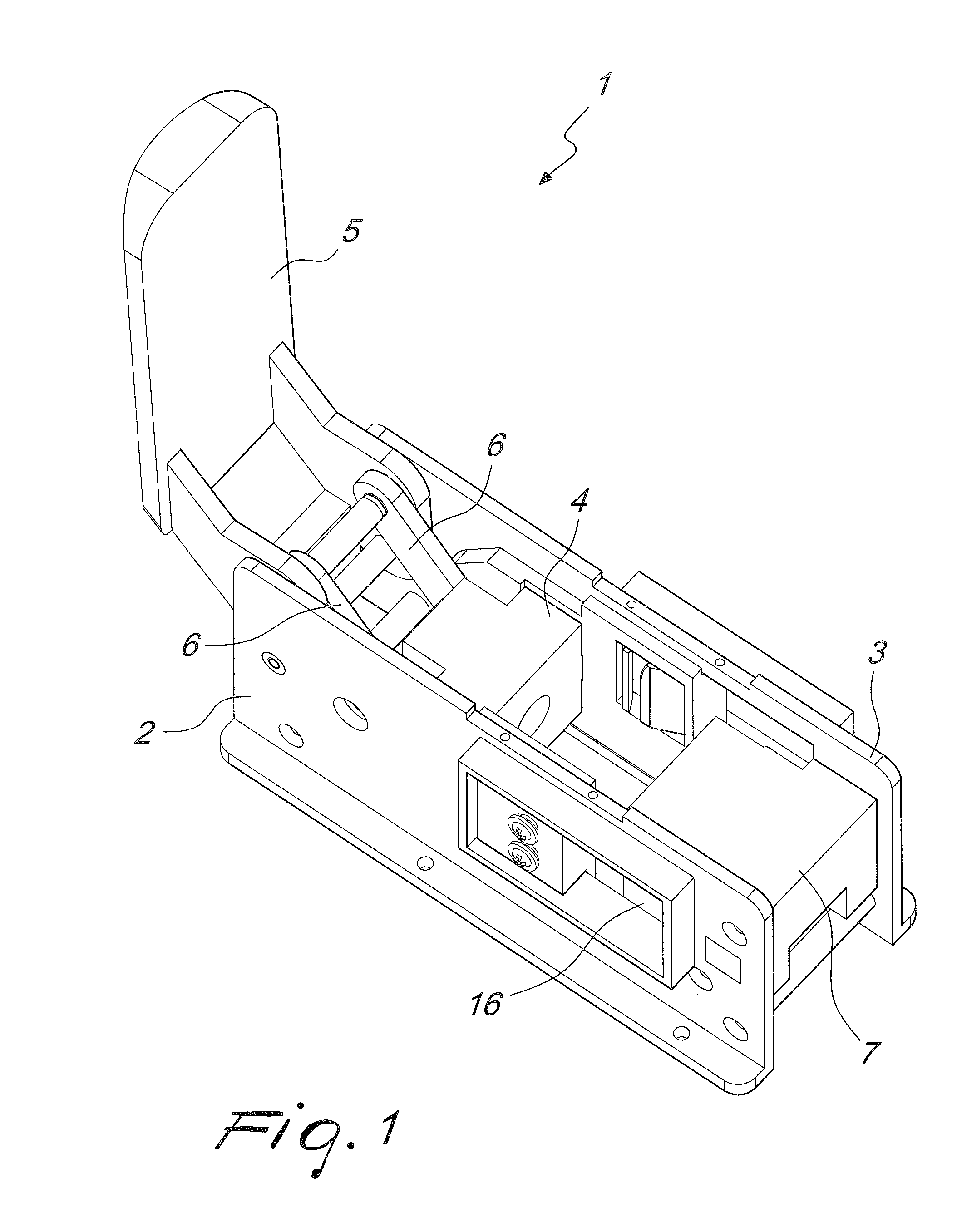
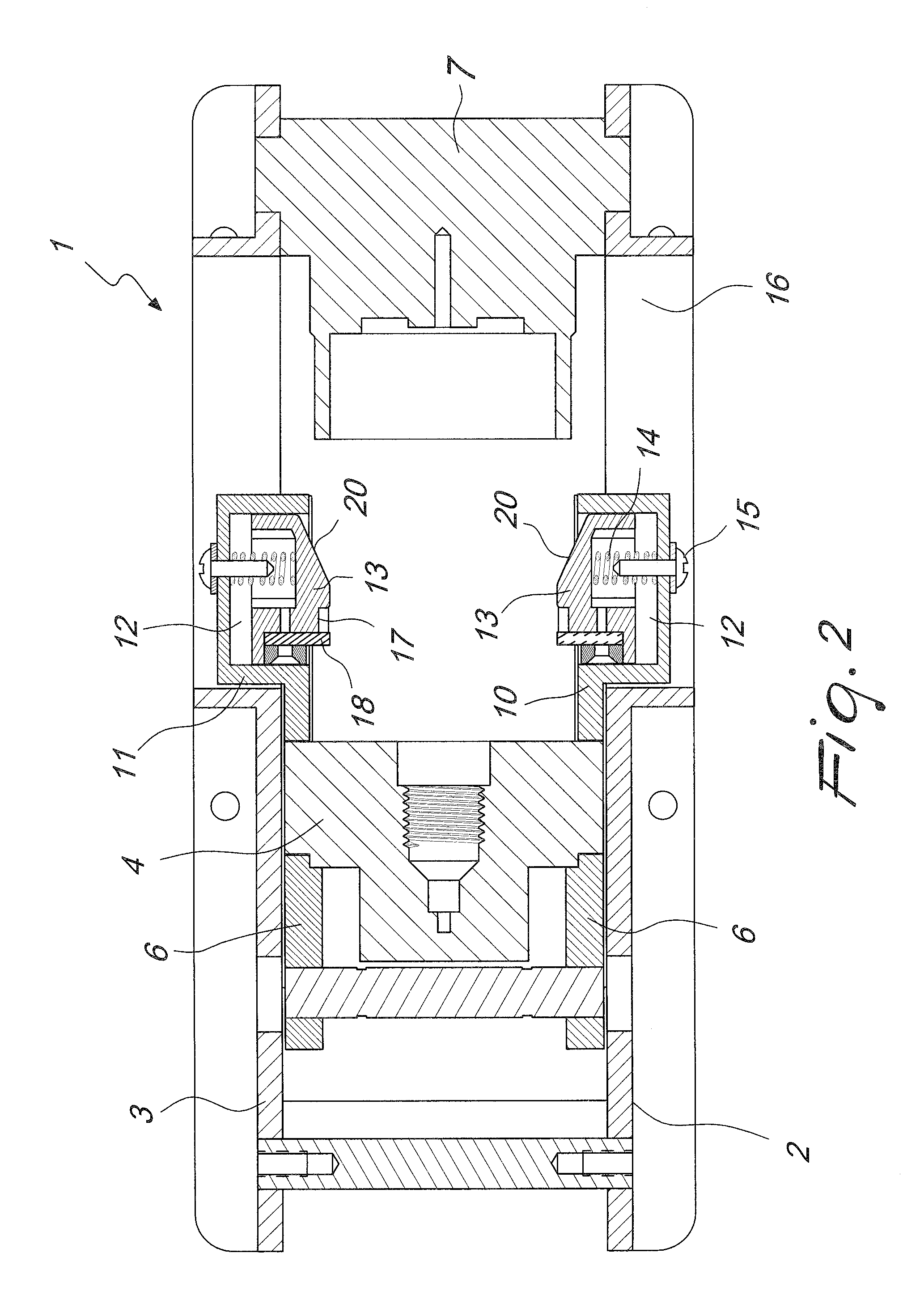
[0032]With reference to the figures, the infusion assembly according to the present invention, thereof, generally designated by the reference numeral 1, comprises two shoulders 2 and 3, which face each other and are adapted to define a space for accommodating internally a piston 4 for supporting a capsule, which is connected to lever means 5 by means of two mutually opposite lever systems 6, which allow the piston 4 to move between the first shoulder 2 and the second shoulder 3 toward and away from a dispensing assembly 7 which is thus fixed.

[0033]Conveniently, means for locking the capsule are connected to the cylinder 4 and are conveniently constituted by an additional pair of shoulders 10 and 11, which form a cavity 12 within which blocks 13 can move elastically transversely with respect to the final extension of the infusion assembly; such blocks can be compressed elastically within the cavity 12 by elastic means 14 which are kept precompressed by screw means 15.

[0034]The addit...

second embodiment

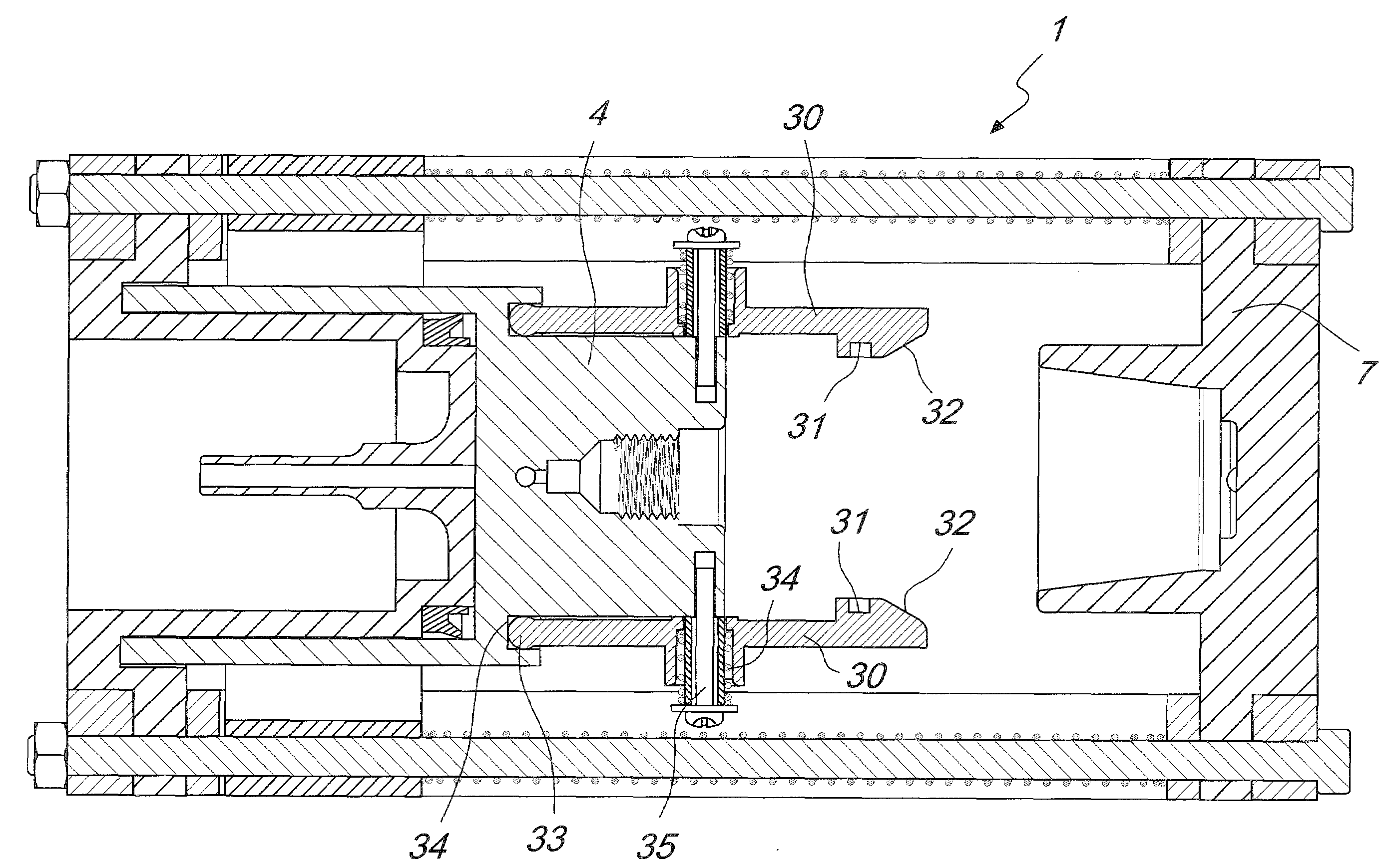
[0042]The second embodiment, shown in FIGS. 4 to 7, is an embodiment in which the actuation of the piston 4 toward the fixed dispensing assembly 7 occurs hydraulically.

[0043]The peculiarity of this second embodiment, in which identical numerals with respect to the first embodiment designate identical or similar elements, is that the piston 4 supports directly the locking means which are constituted by two mutually opposite arms 30 provided with a slot 31 within which the rim of the capsule which contains the preparation for the beverage is inserted, the arms having, at the end of the arm which is not retained, an inclined plane 32 which allows to divaricate the arms 30 when they interfere with the dispensing assembly 7.

[0044]The end of the arms 30 which lies opposite the end of the arm in which the inclined plane 32 is formed has a rounded shape 33, which is accommodated within an appropriately provided seat 34 formed within the body of the piston 4, allowing the rounded part 33 to ...

third embodiment

[0048]FIGS. 8 to 13 are views of the infusion assembly according to the present invention.

[0049]The peculiarity of the third embodiment resides in that means are provided which are adapted to separate the front surface of the capsule 100 from the piston 4.

[0050]When the assembly closes, upon actuation of the lever 5, the means for separating the front surface of the capsule, which are designated by the reference numeral 50, rest against the capsule 100, and in the last part of the movement stroke the means 50 move backwardly until they reach the infusion position, compressing elastic means 51 which are designed to subsequently push again into the initial position, as shown in FIG. 8, the means 50.

[0051]Conveniently, the means 50 are therefore arranged coaxially with respect to the piston 4, can move with the piston 4 and with respect to it thanks to the presence of the elastic means 51.

[0052]FIGS. 9 to 13 show in detail the sequence of movements starting from the initial position sh...


PUM


Abstract

An infusion assembly, particularly for machines for preparing beverages, comprising a first shoulder and a second shoulder which face each other and are adapted to define internally a space for the movement of a piston, a dispensing assembly being arranged between the first and second shoulders, means for locking a capsule being provided, the piston being rigidly coupled to the locking means in order to move the locking means from an open position to a closed position in which the capsule is accommodated within the dispensing assembly.

Description

TECHNICAL FIELD[0001]The present invention relates to an infusion assembly for a beverage preparing machine.[0002]More particularly, the invention relates to an infusion assembly for a machine for preparing beverages such as coffee, tea, cappuccino and the like.BACKGROUND ART[0003]As is known, machines for preparing beverages such as coffee, tea, cappuccino and the like are used both in workplaces and in households and are increasingly widespread owing to the fact that the prepared beverages have a quality which usually is equal to what can be obtained in a bar.[0004]The use of so-called capsules, i.e., specific sealed containers designed to be inserted in an infusion assembly which allows to release the contents of the capsule and thus prepare the beverage for dispensing to the user, with subsequent disposal of the capsule, is also increasingly widespread.[0005]The diffusion of capsules is due to the fact that the user has at his disposal an extremely simple, effective and quick me...

Claims


Application Information

Patent Timeline
Patent Type & Authority Applications(United States)
IPC IPC(8): A47J31/40
CPCA47J31/3638A47J31/3633A47J31/44A47J31/40
Inventor CHENG, ROCKY
Owner PERFECT STEAM APPLIANCE
Why Eureka
Try Eureka