
Pour Cap For Fluid Containers

Inactive Publication Date: 2009-10-08
HYDRAPAK LLC
View PDF13 Cites 14 Cited by
  • Summary
  • Abstract
  • Description
  • Claims
  • Application Information

AI Technical Summary

Benefits of technology

[0007]For switching between the closed position and the open position, a user can rotate the cap counterclockwise about a quarter turn or more. For switching between the open position and the closed position, the user can rotate the cap clockwise to tighten the cap on the threaded neck. In the closed position of the pour cap, the cap body compresses the gasket with a controlled deformation to form the high pressure seal. In the open position of the pour cap, the cap body allows the gasket to restore to an essentially undeformed shape, wherein a fluid flow passage is formed, while the two low pressure seals prevent unwanted fluid flow through the cap body and the threaded ring.

Problems solved by technology

However, this can be inconvenient in many situations, particularly during strenuous activities such as walking, biking or running.
In addition, if the cap is removed from a conventional sports bottle, the fluid is more likely to spill out of the bottle and onto the ground.
Also, the mouth of the bottle has a relatively large diameter, such that during drinking with the cap off, the fluid is prone to splatter onto a person's face and clothes.
Other limitations of the related art will become apparent to those of skill in the art upon a reading of the specification and a study of the drawings.

Method used


Image

  • Pour Cap For Fluid Containers
  • Pour Cap For Fluid Containers
  • Pour Cap For Fluid Containers

Examples


Embodiment Construction

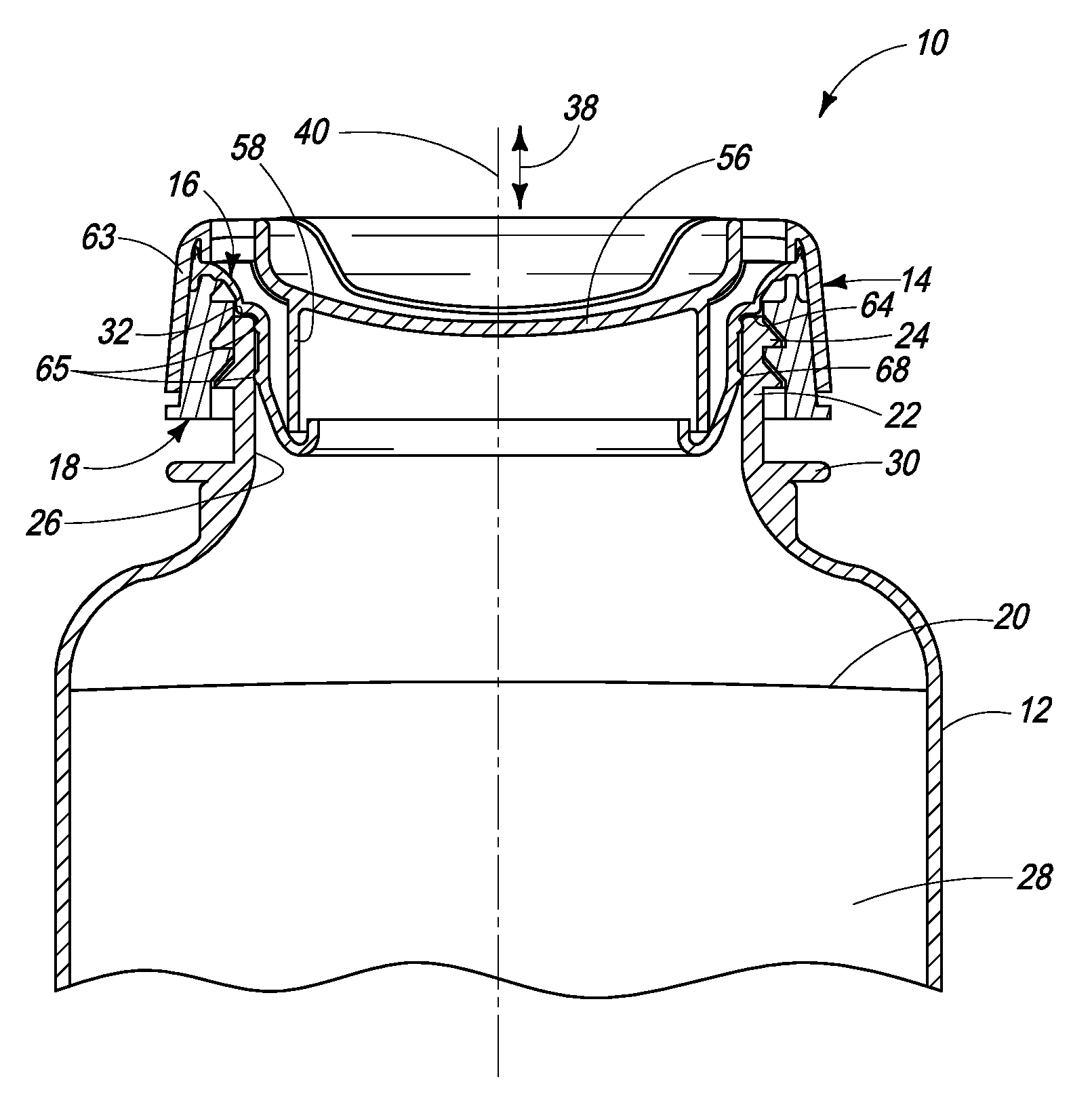
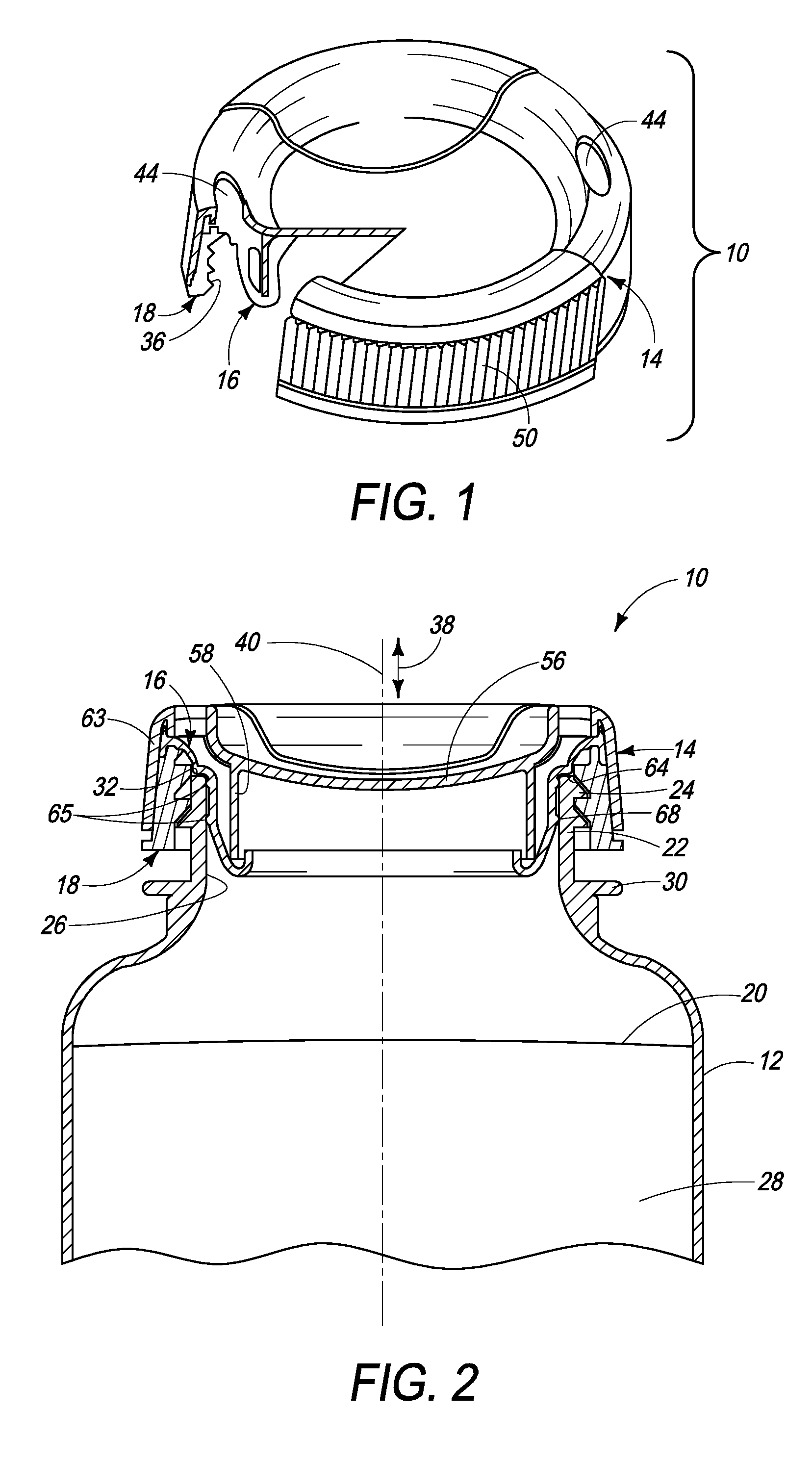
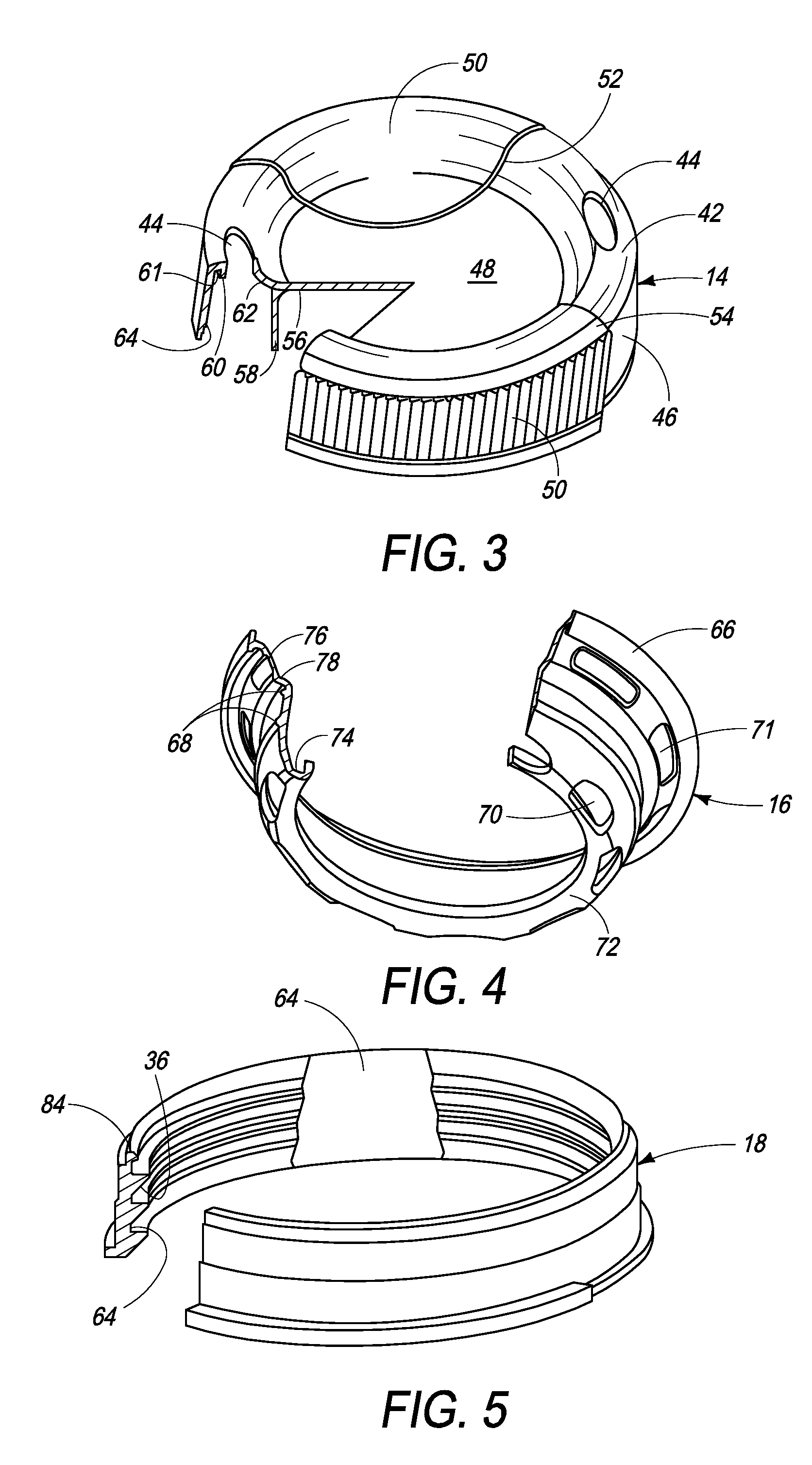
[0031]Referring to FIGS. 1 and 2, a pour cap 10 for a fluid container 12 includes a cap body 14, a gasket 16 mounted to the cap body 14, and a threaded ring 18 attached to the cap body 14. In the pour cap 10 the threaded ring 18 and the cap body 14 comprise separate elements that are bonded together as one. However, it is to be understood that the cap body 14 and the threaded ring 18 can comprise a single piece having a unitary molded construction. Some of the alternate embodiments to be described illustrate a single piece construction.

[0032]As shown in FIG. 2, the fluid container 12 is generally cylindrical in shape having an outside diameter sized for handling by a user, and a body having an interior portion 28 adapted to contain a fluid 20. In the illustrative embodiment, the fluid container 12 comprises an injection blow molded plastic bottle adapted to contain a selected volume of the fluid 20 (e.g., 8-64 oz or 200-2000 ml). However, the fluid container can comprise any suitabl...


PUM


Abstract

A pour cap for a fluid container includes a cap body, a gasket mounted to the cap body, and a threaded ring attached to the cap body. The cap can be positioned on the container in a closed position wherein the container is hydraulically sealed with a high pressure seal, or in an open position wherein fluid flow occurs through flow passages on the gasket and the cap body with first and second low pressure seals preventing unwanted leakage between joining parts on the cap. A method for sealing and pouring a fluid from a container includes the steps of providing the pour cap with the cap body, the gasket and the threaded ring; tightening the cap body to a closed position wherein deformation of the gasket seals the container with a high pressure seal; and then rotating the cap body to an open position wherein the gasket returns to an essentially undeformed state to form a fluid flow passage, while providing first and second low pressure seals for preventing unwanted fluid flow through the cap body and the threaded ring.

Description

FIELD[0001]This application relates generally to caps for fluid containers, and more particularly to a pour cap for fluid containers such as sports bottles.BACKGROUND[0002]Fluid containers, such as sports bottles, provide a fluid source for persons engaged in various activities. Sports bottles typically include a plastic body for containing a fluid, and a cap which threadably attaches to the body. The cap can also include a valve assembly which can be pushed into the cap to seal the fluid, or pulled out of the cap for dispensing the fluid. One aspect of these sports bottles is that the fluid cannot be poured through the valve assembly and out of the bottle into a person's mouth. Rather, the body of the bottle must be squeezed to force the fluid through the valve assembly into the mouth. As the fluid level drops, the bottle must also be manipulated to allow air to flow from the atmosphere through the valve assembly into the bottle.[0003]For pouring the fluid out of a conventional spo...

Claims


Application Information

Patent Timeline
IPC IPC(8): B65B7/28B65D41/04B65D25/40B67D5/00B65D53/00B67D99/00
CPCB65D47/242B65B7/2835
Inventor HEIBERGER, ROBERT A.
Owner HYDRAPAK LLC
Learn More