
Vehicle Barrier

Inactive Publication Date: 2009-10-08
FIBERWEB INC
View PDF98 Cites 33 Cited by
  • Summary
  • Abstract
  • Description
  • Claims
  • Application Information

AI Technical Summary

Benefits of technology

[0010]The present invention provides a vehicle barrier capable of being easily transported and erected, capable of absorbing the impact from a vehicle without significant lateral displacement, and capable of effectively dissipating blast waves from the detonation of an explosive device.
[0012]To enhance the structural integrity of the present invention, each of the impact and reflection sides are formed from a sheet of barrier material. The interior walls are also formed from barrier material. Further, the interior walls are mechanically fastened to the impact and reflection sides (and in some embodiments, each other) to form the chambers. As the barrier is comprised of pliable barrier material, the barrier may be encouraged into a smaller form factor, as compared to its deployed form factor, by collapsing the hollow chambers. However, the deployed form factor of the present invention mandates that the hollow chambers be open and receptive to receiving fill material. Thus, once deployed, the barrier can be packed with fill material, such as soil, sand, or rocks. As the range of fill material accepted by the present invention is so diverse, as discussed hereinbelow, typically, the fill material can be located proximate the erection site (thereby avoiding the requirement to carry heavy fill material).
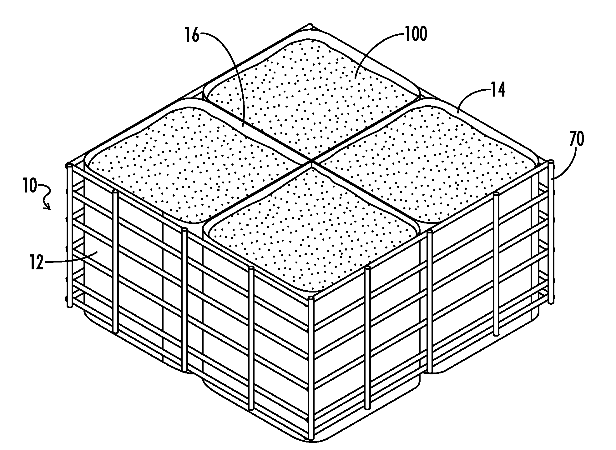
[0014]Although the chambers can be packed individually, the process can be expedited by utilizing a front end loader, a back hoe, a conveyor apparatus, or the like. Because the barrier is an assembly of open interconnected chambers, and the barrier material has enough rigidity to be self-supporting, large amounts of fill material may be deposited in multiple chambers at once with a single effort. Additionally, a light-weight rigid framework may be employed to facilitate the filling process. Such a framework may be coextensive with the perimeter of the barrier and couple to some or all of the chambers comprising the barrier's perimeter. This would allow the framework to provide tension across the plurality of chambers to encourage the chambers into their most exposed, i.e. open, position thereby facilitating the packing / filling process. Further, the framework may be constructed from a set of readily transportable rods or constituent members that interconnect to form the composite framework. Alternatively, the framework may be sized to hold open a single chamber. Such a framework would be compact yet provide a single individual with the ability to easily transport and deploy the framework. However, the present invention is not limited to the frameworks described herein, the present invention also envisions any technique or apparatus that opens the chambers to aid in packing, e.g. tensioning opposing corners / sections of the barrier by manual effort or tie downs.
[0019]Consequently, it is desired to have a vehicle barrier to accept, reflect, and dissipate the forces generated from a vehicle impact or explosion. The barrier material serves this role in the invention. Further, it is desirable to have a barrier that resists being displaced. The interconnected cellular structure of the present invention (which allows the fill material to frictionally engage the ground) provides this capacity. Because of the barrier's resistance to being displaced, and the resultant force experienced by the rapidly decelerated vehicle, the present invention provides the capacity to disable both vehicle and driver so that additional attempts to breach the barrier cannot be conducted.

Problems solved by technology

Chief among these drawbacks is the substantial bulk and weight of the barrier—which limits transportability.
Undesirably, Horton et al. has no provisions for blast protection / dissipation.
As with Beryozkin et al., the weight, form factor, and complexity of Nasatka limits its ability to be easily transported and configured for operation.
However, even these common vehicle barriers have deficiencies.
For example, the New Jersey Barriers can easily be displaced from their original position as the concrete readily slides on hard surfaces, such as roadways, and the sand or water filled drums lack suitable inter-unit connections to effectively disperse the large amount of dynamic energy associated with a vehicle impact or a blast, explosion or ballistic strike.

Method used


Image

  • Vehicle Barrier
  • Vehicle Barrier
  • Vehicle Barrier

Examples


Embodiment Construction

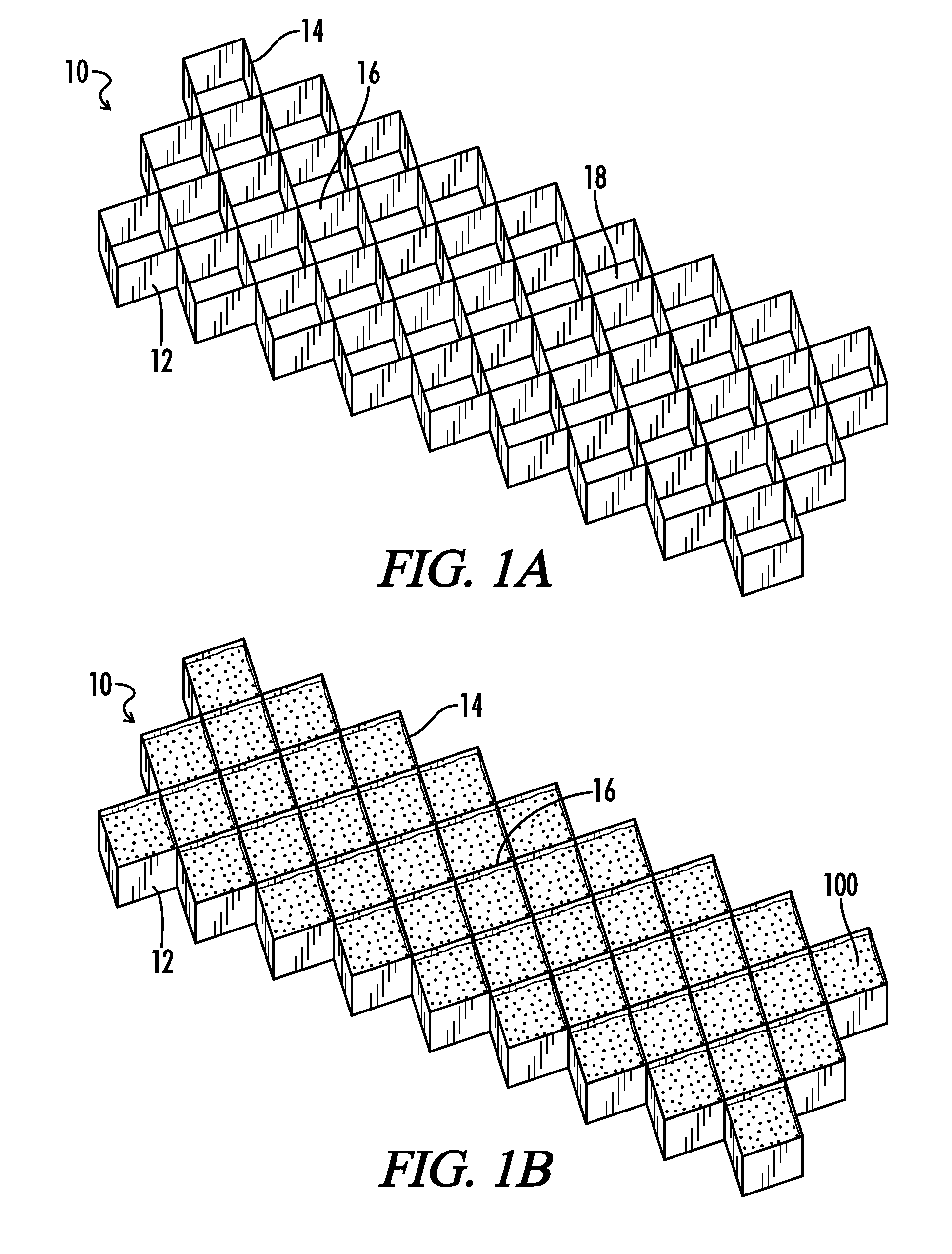
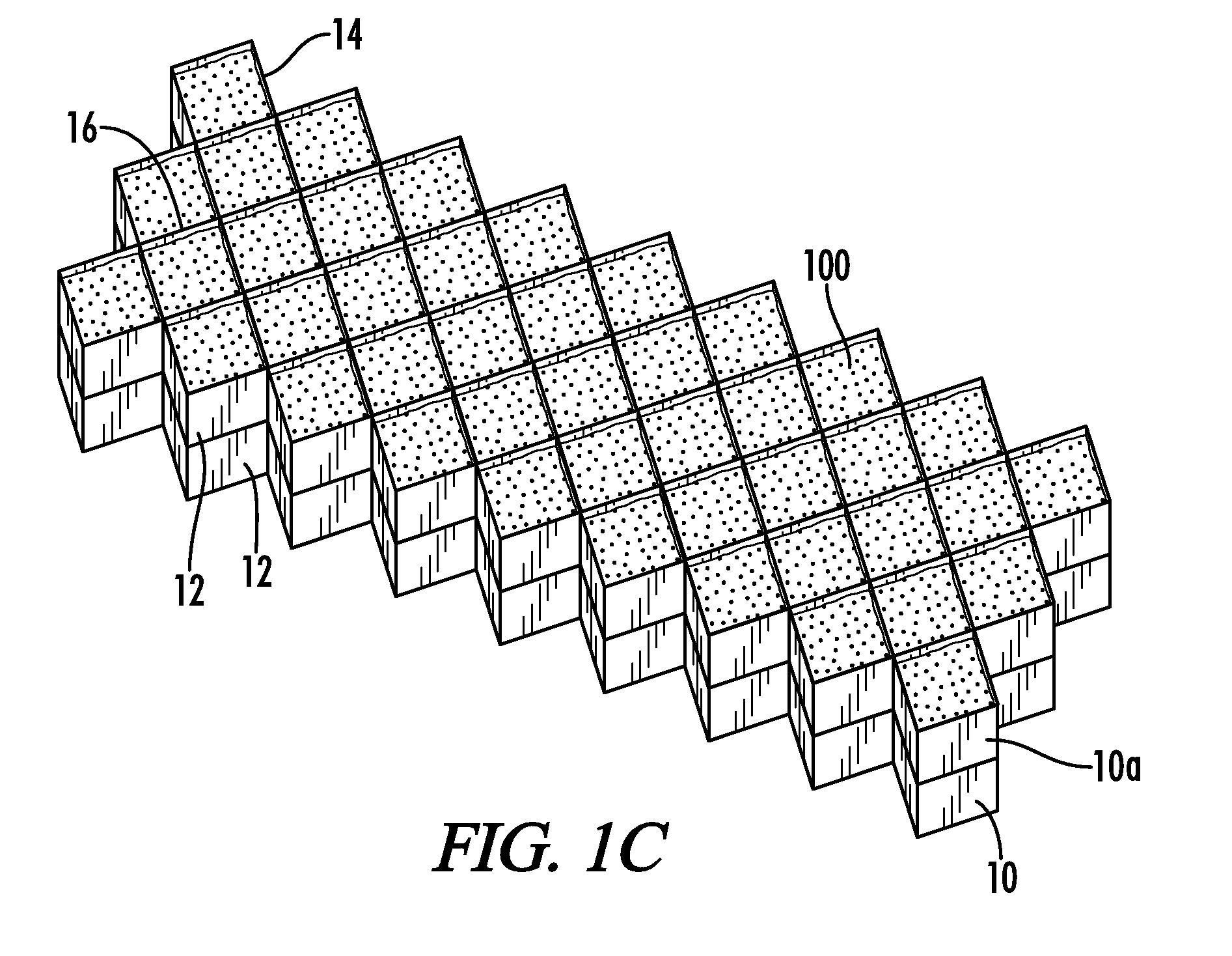
[0030]The present invention relates generally to vehicle barriers and more particularly to portable vehicle barriers. Referring now to the drawings (where, for ease of understanding, not all reference numerals are shown in all drawings), the present invention provides a barrier body 10 having an impact side 12 (i.e., the side of barrier body 10 facing the direction from which an impact is likely to occur), a reflection side 14, and a plurality of interior walls 16, as shown in FIG. 1A. The plurality of interior walls 16 extend between and join the impact side 12 and the reflection side 14. The plurality of interior walls 16, the impact side 12, and the reflection side 14 are arranged to form a plurality of hollow protection chambers 18 or plurality of vessels 18, which, in application, are filled with a fill material 100.

[0031]The vertical sides of the plurality of hollow protection chambers 18 are defined by either the plurality of interior walls 16 or some combination of the plura...


PUM


Abstract

A vehicle barrier having an impact side, a reflection side opposite the impact side, and a plurality of interior walls extending between the impact side and the reflection side. The refection side, the impact side, and the plurality of interior walls are formed from vertically-oriented sheets of barrier material (when in the deployed configuration). Further, the refection side, the impact side, and the plurality of interior walls define multiple chambers. The chambers can be packed with fill material to stop an oncoming vehicle.

Description

CROSS-REFERENCE TO RELATED APPLICATIONS[0001]This application is a continuation-in-part application which claims benefit of co-pending U.S. patent application Ser. No. 12 / 053,966 filed Mar. 24, 2008, entitled “BALLISTICS BARRIER” which is hereby incorporated by reference.TECHNICAL FIELD[0002]The present invention relates to vehicle barriers. More specifically, the present invention pertains to barriers that can effectively arrest the movement of an oncoming vehicle and dissipate blast / impact waves created from the impact of the vehicle and / or the detonation of explosives carried by the vehicle. Further, the present invention relates to vehicle barriers that are readily transportable and can be expeditiously erected.BACKGROUND OF THE INVENTION[0003]The applications for vehicle barriers range from routing the flow of traffic to preventing vehicles from entering a restricted roadway to providing a barricade limiting vehicle proximity to a building or other sensitive locale. In addition...

Claims


Application Information

Patent Timeline
IPC IPC(8): E01F15/00
CPCE01F15/145E01F13/12
Inventor CASHIN, ARTHUR HENRYHAWKINS, SHELDRICK FARISHAWKINS, WILLIAM MCADAMHICKLE, BRIAN ANDREWVERBLE, MARC DOUGLASHOLLOWELL, JR., FRANK LEE
Owner FIBERWEB INC
Learn More