
Backlight Module

a backlight module and module technology, applied in the field of backlight modules, can solve the problems of large influence on the performance of products, inconvenient use, and inability to accurately measure the orientation of assembly measures, so as to prevent material or time waste, facilitate the use of personnel, and prevent material defects

Inactive Publication Date: 2009-10-08
FORWARD ELECTRONICS CO LTD
View PDF0 Cites 4 Cited by
  • Summary
  • Abstract
  • Description
  • Claims
  • Application Information

AI Technical Summary

Benefits of technology

[0012]With help of the above-mentioned structure, it is understood that during the steps in assembling the light bar, not only personnel are facilitated in the assembly work, but also the light bars having lighting units of defective orientation can, in the meantime, be sieved out during the assembly process. This will prevent the defect of material or time waste if illumination test is performed only after the whole backlight module has been finished.
[0013]An illumination surface of each of the plural lighting units and an opening of its corresponding locating groove are spaced apart from with a predetermined distance so as to assure uniformity of illumination. The locating grooves include at least one through groove, or at least one blind groove. The lighting unit located at the blind groove abuts upon a rear wall of the blind groove. This will provide the light bar, when in assembly, with an orientating function in a longitudinal direction. By means of this longitudinal orientation measure, a predetermined distance can be maintained between the lighting unit and the opening of the locating groove.

Problems solved by technology

However, such an assembling measure is quite inaccurate in orientation.
In spite of the fact that the angle of deviation may be minor, influence on the performance of products, however, is very significant.
It would be quite cost consuming if inspection is carried out on orientation of all the LED lighting units 5 disposed on the circuit board 4.
Or if illumination test is performed only after the whole LED backlight module has been finished, it would be very material waste in case there is a defect on the orientation of the LED lighting units 5 for the reason that the whole LED backlight module is to be abandoned.

Method used


Image

  • Backlight Module
  • Backlight Module
  • Backlight Module

Examples


Embodiment Construction

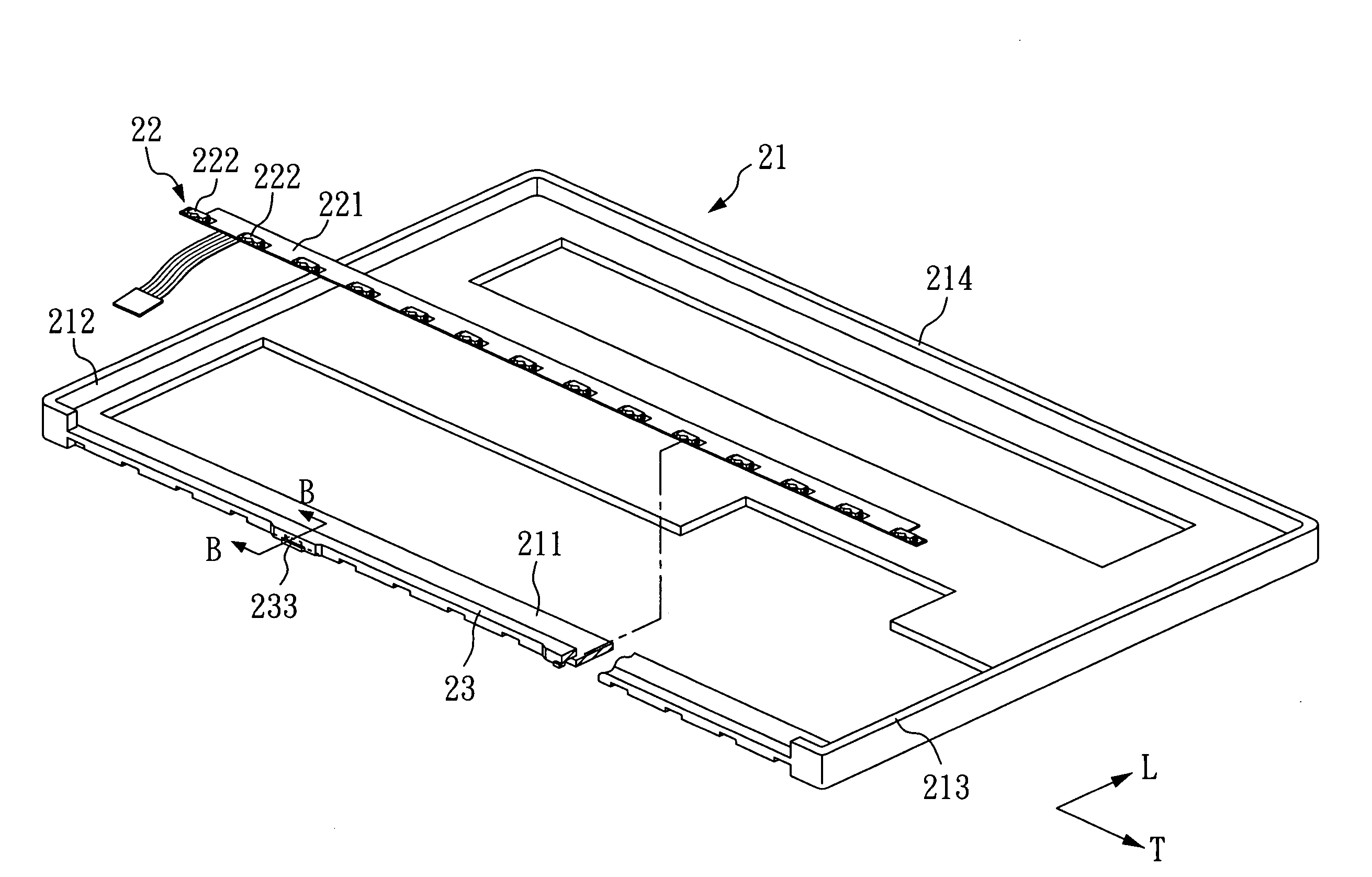
[0021]Referring to FIGS. 3 and 4, perspective views illustrating a backlight module according to the present invention in different view angles, an edge-lighting LED backlight module includes a frame 21 and a light bar. The frame 21 includes two sides 212,213 parallel with and opposed to each other, a support 211 connected between the two sides 212,213, and a connecting segment 214 parallel with and opposed to the support 211 and likewise connected with the two sides 212,213. The four parts, as mentioned above, constitute together the frame 21 having a rectangular contour.

[0022]In the frame 21 and at the same side as the support 211, there is also provided with a locating bar 23 which is likewise connected between the two sides 212,213. The support 211, the two sides 212,213, the connecting segment 214, and the locating bar 23 are made integrally in one piece.

[0023]The light bar refers to an LED light bar 22 including a circuit board 221 and a plurality of LED lighting units 222, wh...


PUM


Abstract

A backlight module includes a frame, a light bar, and a locating bar. The locating bar is connected between two sides of the frame. The light bar includes a circuit board and a plurality of lighting units, where the circuit board is secured on a support of the frame, and where the plural lighting units are engaged with plural locating grooves of the locating bar, such that the lighting units are confined by the locating grooves in a lateral direction. Therefore, during the steps in assembling the light bar, not only personnel are facilitated in the assembly work, but also the light bars can be sieved out during the assembly process, preventing the defect of material waste if illumination test is performed only after the whole backlight module has been finished.

Description

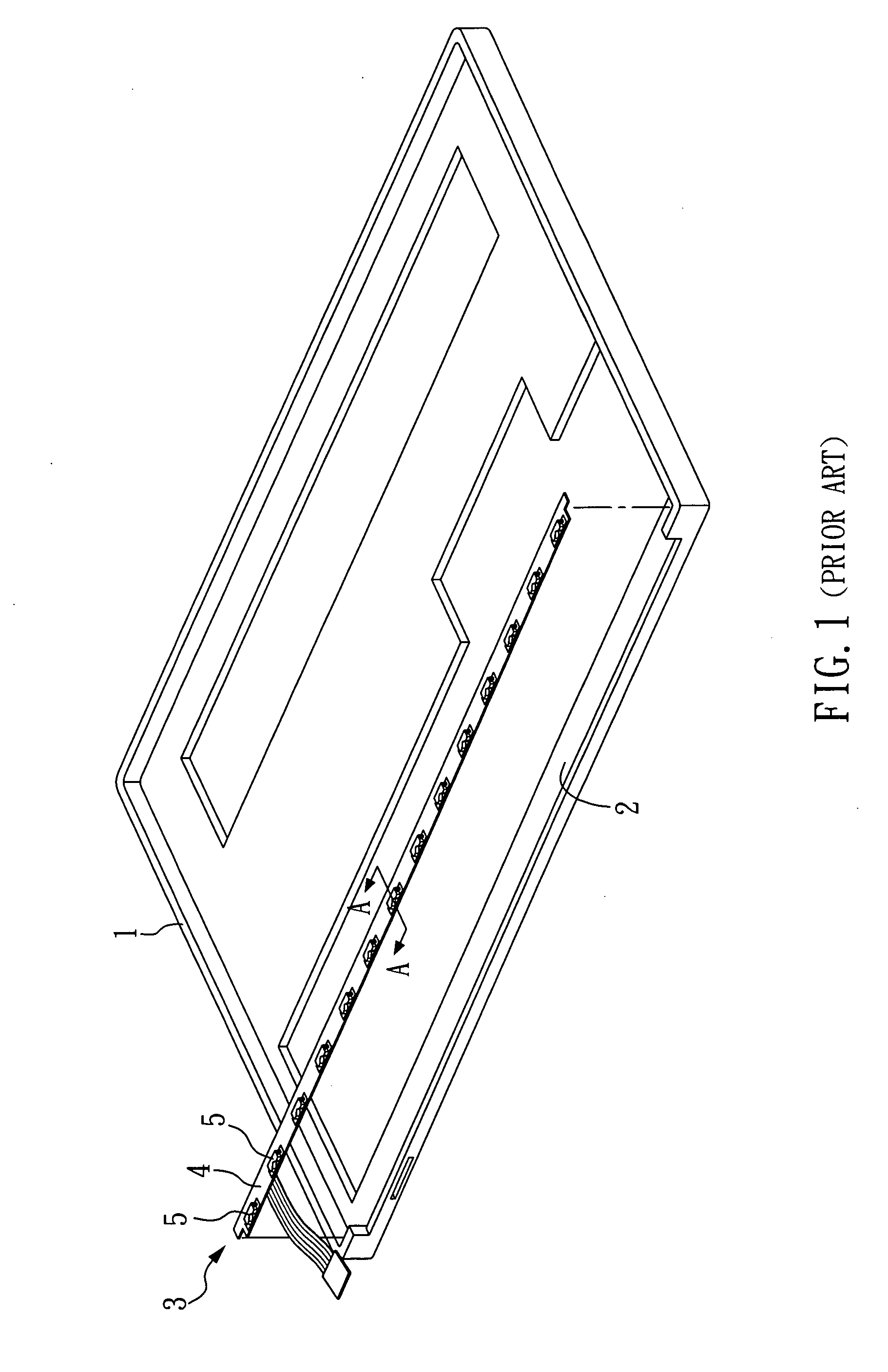
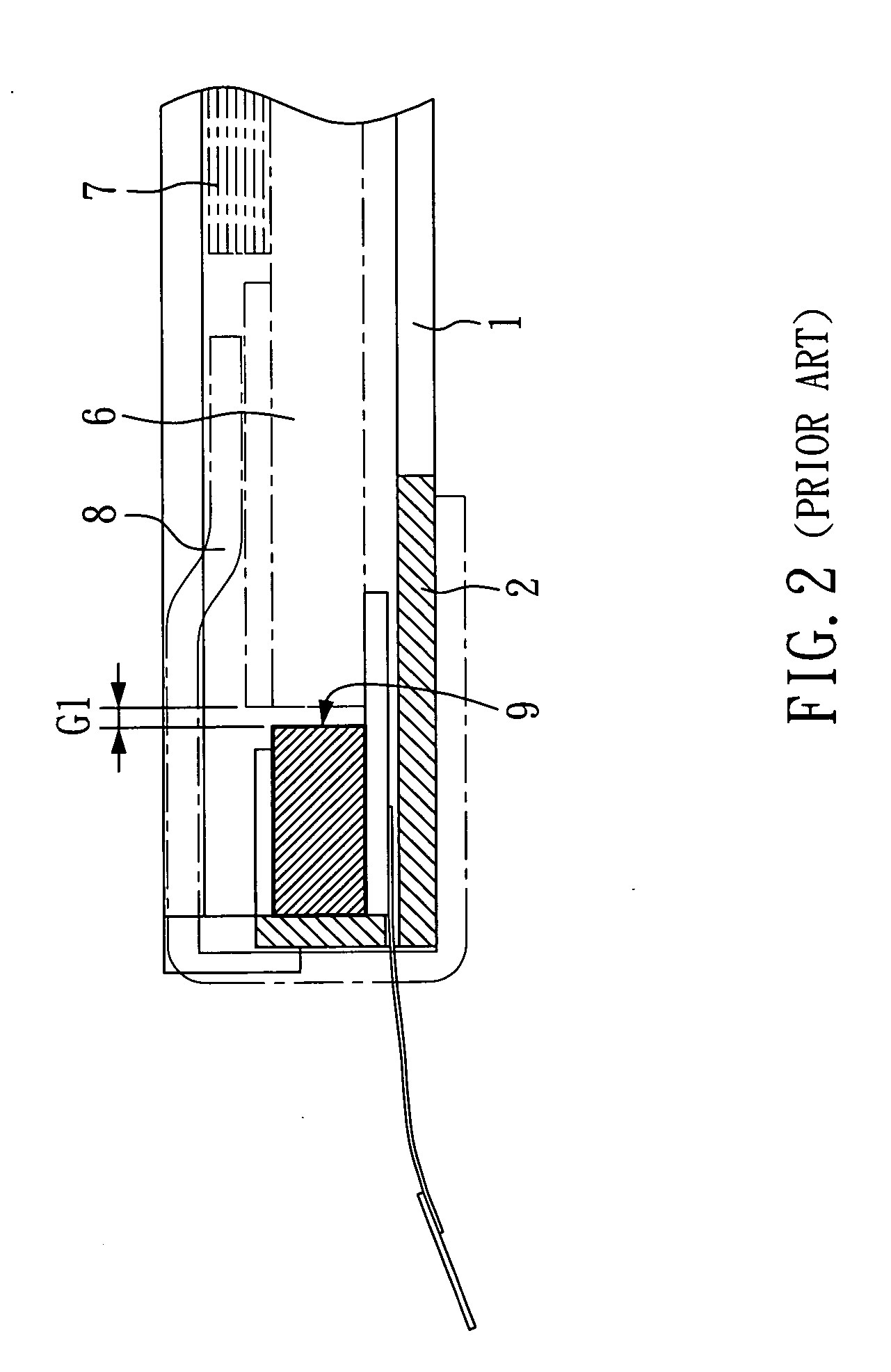
BACKGROUND OF THE INVENTION[0001]1. Field of the Invention[0002]The present invention relates to a backlight module, and more particularly, to an edge-lighting backlight module where an LED (light emitting diode) light bar can be assembled and orientated conveniently.[0003]2. Description of Related Art[0004]Conventionally, the measure in assembling an LED light bar includes securing the LED light bar on a light guide; or securing the LED light bar on the side of a plastic frame (as shown in FIG. 1). Referring to FIGS. 1 and 2, a perspective view illustrating a conventional backlight module and a cross-sectional view taken along cutting line A-A of FIG. 1, an LED light bar 3 includes a circuit board 4 and a plurality of LED lighting units 5 fixed on the circuit board 4. The LED light bar 3 is, with the circuit board 4, attached to the support 2 of a frame 1. The support 2 also provides a supporting function for other components, including, for example, a reflecting film (not shown).[...

Claims


Application Information

Patent Timeline
Patent Type & Authority Applications(United States)
IPC IPC(8): G09F13/08
CPCG02B6/0083G09F13/18G02B6/0091
Inventor YEN, CHAO-SHIHLEE, CHIEN-TONGTSAI, YAO-TSUNG
Owner FORWARD ELECTRONICS CO LTD
Learn More