Torque sensor device

a technology of torque sensor and torque sensor, which is applied in the direction of force/torque/work measurement apparatus, instruments, transportation and packaging, etc., can solve the problems of increasing the possibility of erroneous operation, increasing manufacturing cost, and different rotation amounts of steering wheel and vehicle wheel with each other, so as to reduce manufacturing cost, reduce process cost and assembly errors, and improve assembly. the effect of quality

Active Publication Date: 2018-09-04
LS AUTOMOTIVE TECH CO LTD
View PDF27 Cites 6 Cited by
  • Summary
  • Abstract
  • Description
  • Claims
  • Application Information

AI Technical Summary

Benefits of technology

[0038]The torque sensor device according to the embodiments of the present invention as constructed above have the following advantageous effects.
[0039]First, the torque sensor device of the present invention can take a plurality of shield ring pieces of an insertable mounting structure to achieve automation, if necessary, through the improvement of assemblability, thereby minimizing the process cost and assembly errors and achieving the cost reduction.
[0040]Second, the torque sensor device of the present invention can minimize the generation of scraps in the process of manufacturing the shield ring pieces through an optimized structure of the shield ring pieces, thereby preventing the waste of materials and achieving the cost reduction.
[0041]Third, the torque sensor device of the present invention can prevent the escape of the plurality of shield ring pieces in a subsequent process through a heat-fusion process after the insertion of the shield ring pieces, thereby ensuring a stable assembly and manufacture process.
[0042]Fourth, the torque sensor device of the present invention can implement a stable mounting structure through the over-molding process of the shield ring body after insertion of the shield ring pieces into the shield ring body.
[0043]Fifth, the torque sensor device of the present invention can take a primary molding structure during the formation of the shield ring body in the over-molding process of the shield ring body after the insertion of the shield ring pieces into the shield ring body, and avoid the possibility of occurrence of a defect and erroneous operation due to an unwanted separation and escape or a change of constituent elements and enhance durability period to ensure reliability of products through a secondary molding structure in the over-molding process of the shield ring body after the insertion of the shield ring pieces.

Problems solved by technology

However, because the vehicle wheel is in contact with the road surface, there may be a problem that rotation amounts of the steering wheel and the vehicle wheel become different with each other due to a friction generated between the vehicle wheel and the road surface.
However, the conventional contactless type torque sensor encounters problems in that an excessive number of constituent elements are required and an assembly process is complicated, thus leading to increases in the possibility of erroneous operation and the manufacturing cost, and to an exposure of a problem associated with durability period of the torque sensor due to the excessive number of constituent elements.

Method used


Image

  • Torque sensor device
  • Torque sensor device
  • Torque sensor device

Examples


Embodiment Construction

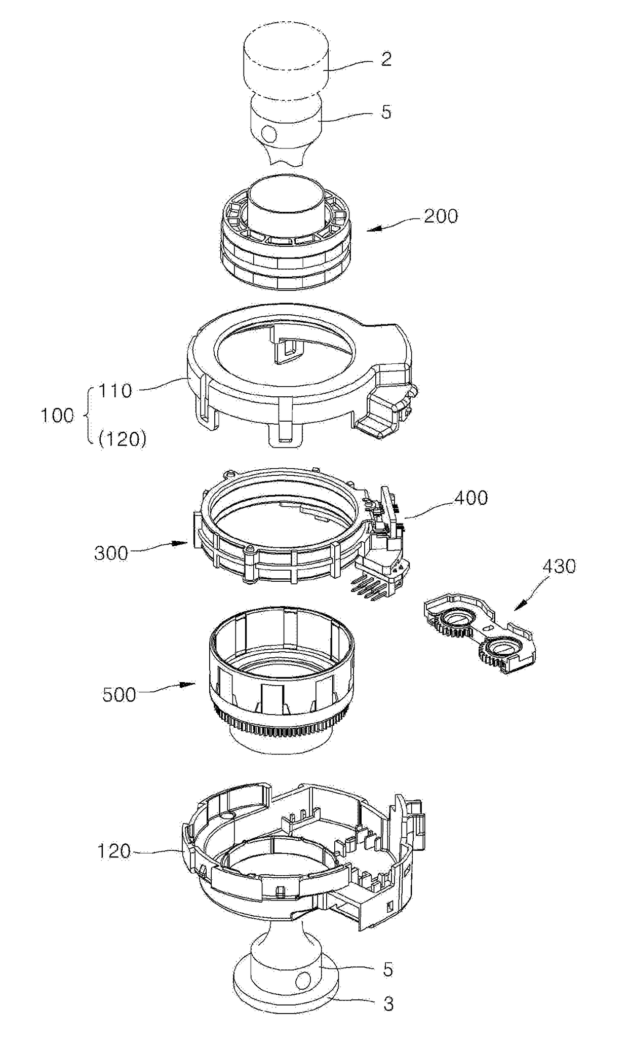
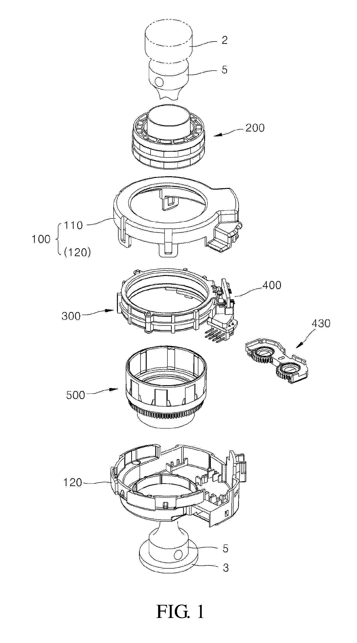
[0103]Hereinafter, the configuration and operation of a torque sensor device 10 of the present invention will be described in detail with reference to the accompanying drawings.

[0104]The torque sensor device 10 of the present invention includes a housing 100, a magnet unit 200, a collector unit 300, a sensing unit 400, and a shield ring unit 500. The torque sensor device 10 of the present invention is disposed between an input shaft 2 and an output shaft 3 and detects a torque between the input shaft 2 and the output shaft 3 through a relative rotation displacement therebetween.

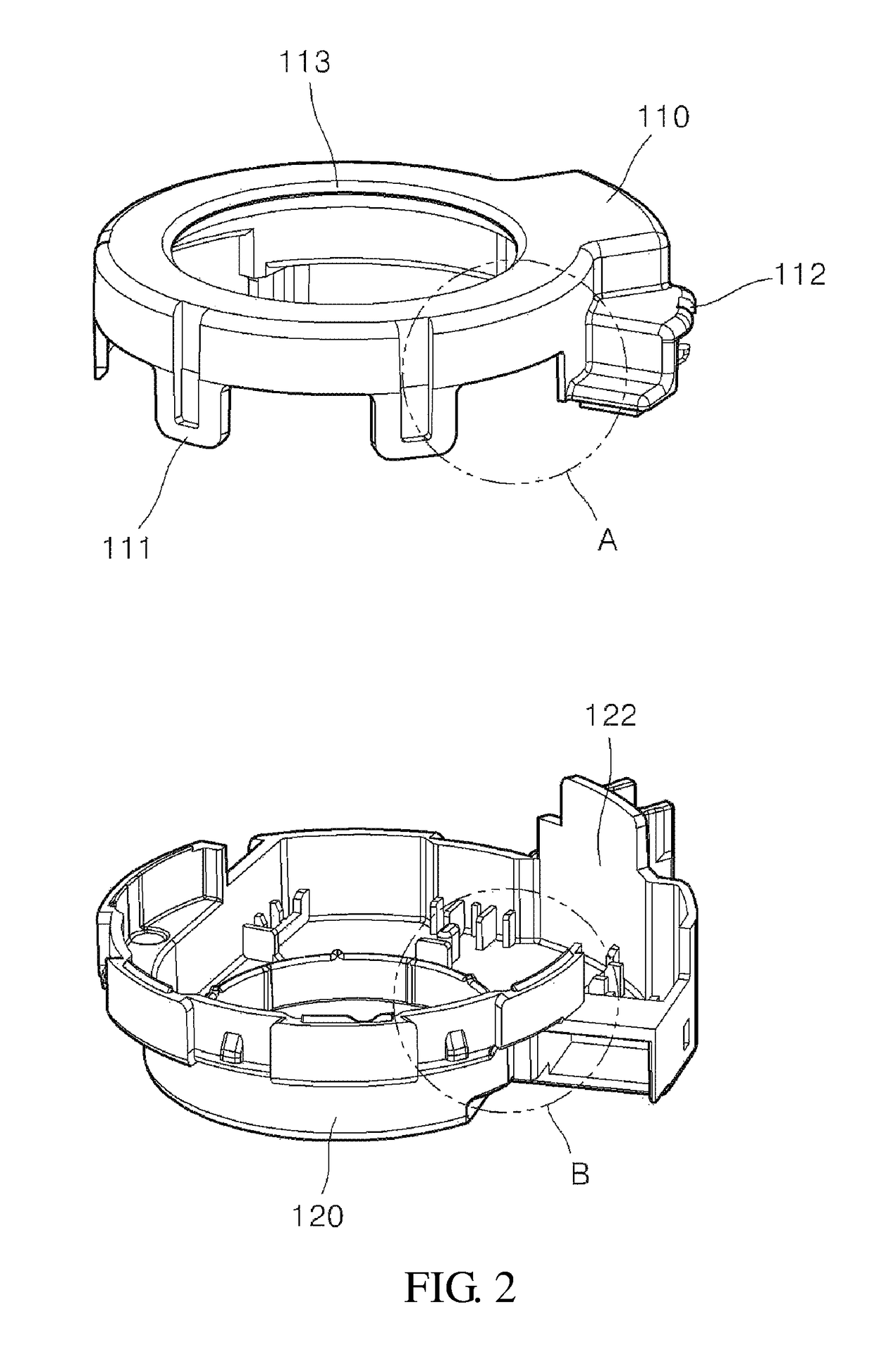
[0105]The housing 100 accommodates an end of the input shaft 2 and an end of the output shaft 3 and is fixed in position to be able to perform a relative rotation with respect to the input shaft 2 and the output shaft 3.

[0106]The magnet unit 200 is accommodated in the housing and includes a magnet ring 220 connected to one end of the input shaft 2 so as to be rotatably accommodated in the housing 100.

[0107]Th...


PUM

PropertyMeasurementUnit
torqueaaaaaaaaaa
magnetic fieldaaaaaaaaaa
outer circumferenceaaaaaaaaaa

Abstract

The present invention provides a torque sensor device disposed between an input shaft and an output shaft and configured to detect a torque between the input shaft and the output shaft through a relative rotation displacement therebetween. The torque sensor device includes: a housing configured to accommodate an end of the input shaft and an end of the output shaft and fixed in position to be able to perform a relative rotation with respect to the input shaft and the output shaft: a magnet unit accommodated in the housing and including a magnet ring connected to one end of one of the input shaft and the output shaft so as to be rotatably accommodated in the housing; a collector unit fixed in position to the housing in such a manner as to be disposed at the outside of the magnet unit, and configured to focus a magnetic field generated from the magnet unit; a sensing unit including a torque sensor disposed at the outer circumference of the collector unit and configured to detect the magnetic field focused by the collector unit; and a shield ring unit interposed between the collector unit and the magnet unit in such a manner as to be connected to one end of the other of the input shaft and the output shaft, and configured to change the magnetic field from the magnet unit, which is focused by the collector unit, by means of the relative rotation between the input shaft and the output shaft.

Description

TECHNICAL FIELD[0001]The present invention relates to a torque sensor, and more particularly, to a torque sensor for detecting a torque applied to a shaft including an input shaft and an output shaft.BACKGROUND ART[0002]In general, a vehicle wheel which is in contact with a road surface rotates according to a rotation of a steering wheel during traveling or stopping of a vehicle. In other words, when the steering wheel rotates to the left or right, the vehicle wheel rotates in the same direction as the rotation direction of the steering wheel. However, because the vehicle wheel is in contact with the road surface, there may be a problem that rotation amounts of the steering wheel and the vehicle wheel become different with each other due to a friction generated between the vehicle wheel and the road surface. For this reason, a driver needs a large force to manipulate the steering wheel.[0003]The vehicle includes a power steering (PS) system as a steering force auxiliary device. In t...

Claims


Application Information

Patent Timeline
Patent Type & Authority Patents(United States)
IPC IPC(8): G01L3/00G01L3/10B62D15/02
CPCB62D15/021G01L3/101G01L3/10B62D6/10G01L5/221G01L3/104G01L5/22B62D15/02
Inventor LEE, WON YONGCHO, YEONG WOONKIM, SEONG IKKIM, SE HWANKIM, YU CHANPARK, KON HO
Owner LS AUTOMOTIVE TECH CO LTD
Why Eureka
Try Eureka