
Ceramic or glass-ceramic article and methods for producing such article

a technology of ceramics and glass ceramics, applied in the direction of synthetic resin layered products, natural mineral layered products, nuclear engineering, etc., can solve the problems of inability difficult to meet the requirements of small quantity, and few economically viable methods are known. , to achieve the effect of simple preparation, simple determination of final composition, and simple mixing of separate powders

Active Publication Date: 2017-01-31
FRAUNHOFER GESELLSCHAFT ZUR FOERDERUNG DER ANGEWANDTEN FORSCHUNG EV +3
View PDF29 Cites 6 Cited by
  • Summary
  • Abstract
  • Description
  • Claims
  • Application Information

AI Technical Summary

Benefits of technology

The present invention provides an improved method for the free form production of ceramic or glass-ceramic articles. This method can avoid waste of material, making it economically viable for prototype production, and can produce articles with improved bending strength, hardness, smoothness of surface, fracture toughness, fracture strength, biocompatibility and / or reduction of overall pore volume. Additionally, the method can produce dense ceramic or glass ceramic material without the necessity of subsequent sintering or a subsequent glass infiltration process, and can prevent damage such as cracks and fissures. The method can also enable the production of complex three-dimensional structures that cannot be produced by subtractive methods of production.

Problems solved by technology

Corresponding methods most of the time require complex processes involving the production of molds or the like.
For commercial reasons, these production methods are generally unacceptable for small quantities.
For prototyping, the production of small series of ceramic or glass-ceramic articles or the production of a plurality of articles each having different shape, only few economically viable methods are know.
The problems associated with these production methods are large initial investment, waste of material and tool wear.
The latter is costly and reduces accuracy of the articles produced.
One method to produce shaped ceramic or glass-ceramic articles is computer controlled milling of shaped bodies out of the solid ceramic or glass-ceramic material, which inevitably leads to considerable waste that has to be reprocessed at great effort and expense.
Also, complicated shapes with deep hollows are not accessible by the aforementioned methods or require complex procedures.
However, ceramic or glass-ceramic articles produced by such known methods often have a fairly large amount of cracks, fissures and other imperfections, and therefore have inferior properties, especially inferior mechanical properties, inferior biocompatibility, high porosity and the like and are therefore not suited for sophisticated applications, e.g. as dental article or in certain applications in the electronic industry.
The often inferior properties of ceramic or glass-ceramic articles produced by such methods are primarily a result of the very high melting points of ceramic materials.
These melting points make rapid rates of heating and cooling of the material necessary and result in large temperature differences among different parts of the articles produced during the production process.
This leads to high stresses inside the ceramic or glass-ceramic articles which in turn lead to cracks, fissures and other defects.
This may lead to evaporation, in particular explosive evaporation, on the side of the layer heated by the beam, while the side of the layer facing away from the beam may not even be molten.
However, until to date no method of free form fabrication is known for the preparation of ceramic or glass-ceramic articles with similar or even better material properties than those produced by the above mentioned subtractive machining methods.

Method used


Image

  • Ceramic or glass-ceramic article and methods for producing such article
  • Ceramic or glass-ceramic article and methods for producing such article
  • Ceramic or glass-ceramic article and methods for producing such article

Examples


example 1

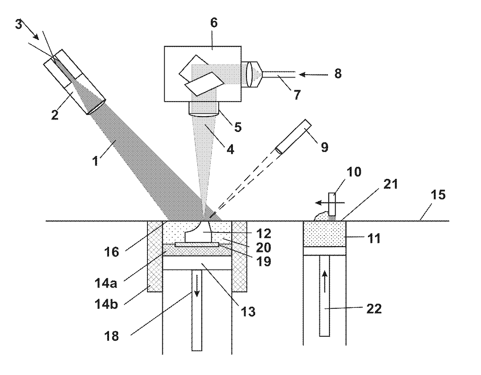
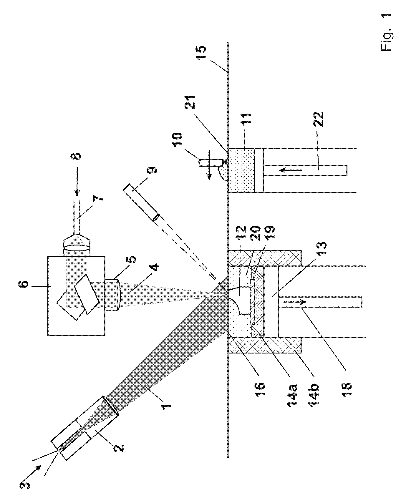
[0346]A powder “Zaspher 260M™” (available from Innalox bv, 5932 NB Tegelen, The Netherlands) consisting of spherical powder particles of a diameter d50 of 35 μm prepared by condensation from the gas phase is used. The powder consists of 39.5% by weight ZrO2, 1% by weight Y2O3 and 59.5% by weight Al2O3. In the selective laser melting apparatus according to FIG. 1 a layer of the powder with a thickness of approx. 100 μm is deposited on a ceramic substrate of the dimensions 18 ×18 ×3 mm3 produced by conventional sintering of the same powder. The powder layer and the substrate are preheated to a temperature of 1700° C. at a rate of 2 K / s by a CO2-laser beam (1). The preheating to 1700° C. is done only once in the beginning of the build up process and then the preheating temperature is maintained approximately constant at 1700° C. during the whole build up process. The laser beam is incident on the substrate and an area surrounding the substrate and the intensity is homogeneous within th...

example 2

Powder Composition 80% ZrO2, 20% Al2O3

[0348]2.1 Preparation of Article (with Glass Infiltration, without Preheating)

[0349]A powder consisting of 80% by weight of zirconia and 20% by weight of alumina powder with a powder particle size between 25 μm and 45 μm and a d50 value of 35 μm is prepared by mixing two powders prepared separately by crushing, grinding and sieving a solidified alumina melt and a solidified zirconia melt, respectively. In a selective laser melting apparatus a layer of the powder with a thickness of approx. 100 μm is deposited on an aluminium substrate. Subsequently a focussed CO2 laser beam is used to selectively melt regions of the powder layer. The beam diameter is 300 μm on the surface of the powder layer. To melt the powder or powder mixture in the desired regions, the focus of the laser beam (4) is moved in straight adjacent lines over area of the substrate whereby each two adjacent lines overlap by 190 μm at a speed of 100 mm / s. The laser power is set to ...

example 3

Powder Composition 80% ZrO2, 20% Al2O3

[0357]3.1 Preparation of Article (with Glass Infiltration, without Preheating), Examination of Precipitation Behaviour

[0358]The experimental conditions are as described in Example 2.1 The precipitation behaviour in a region is examined in more detail, after the laser has been switched off:

[0359]It is observed that ZrO2 crystals precipitate first from the melt, as soon as the temperature falls below 2200° C. This way the ZrO2 content in the melt is continuously reduced during further cooling down to a temperature of 1860° C. At that temperature, the remaining melt has exactly the eutectic composition (41.5 wt. % ZrO2 / 58.5 wt. % Al2O3). This melt represents 30.4 wt. % of the total mass of the deposited powder. When this eutectic melt finally solidifies, a fine grained two phase microstructure with grain sizes smaller than 1 μm is formed. The larger ZrO2 crystals solidified earlier are embedded in this fine grained matrix.

[0360]3.2 Preparation of ...


PUM

PropertyMeasurementUnit
Temperatureaaaaaaaaaa

Abstract

The present invention relates to a method of producing a (shaped) ceramic or glass-ceramic article, involving the steps of: (a) providing a powder or a powder mixture comprising ceramic or glass-ceramic material, (b) depositing a layer of said powder or powder mixture on a surface, (d) heating at least one region of said layer by means of an energy beam or a plurality of energy beams to a maximum temperature such that at least a part of said ceramic or glass-ceramic material in said at least one region is melted and (e) cooling said at least one region of said layer so that at least part of the material melted in step (d) is solidified, such that the layer is joined with said surface in said at least one region. The invention also relates to ceramic or glass-ceramic articles and their use.

Description

CROSS-REFERENCE TO RELATED APPLICATIONS[0001]This application is a §371 national stage entry of International Application No. PCT / EP2010 / 061637, filed Aug. 10, 2010, which claims priority to European Patent Application No. EP 09167581.9, filed Aug. 10, 2009, the entire contents of which are incorporated herein by reference.FIELD OF THE INVENTION[0002]The present invention relates to a method of producing a (shaped) ceramic or glass-ceramic article, in particular a dental article or an article for use in the electronic industry, refractory industry, chemicals industry, aerospace industry or food industry. The method involves the steps of: (a) providing a powder or a powder mixture comprising ceramic or glass-ceramic material, (b) depositing a layer of said powder or powder mixture on a surface, (d) heating at least one region of said layer by means of an energy beam or a plurality of energy beams to a maximum temperature such that at least a part of said ceramic or glass-ceramic mate...

Claims


Application Information

Patent Timeline
IPC IPC(8): B05D3/06B22F3/105A61K6/027A61K6/02C23C24/10C23C24/00C04B35/653C04B35/488C04B35/119C04B35/109B29C67/00B28B1/00B23K26/00B23K26/08
CPCC23C24/10A61K6/024A61K6/025A61K6/0215A61K6/0255A61K6/0273B22F3/105B23K26/00B23K26/08B28B1/00B28B1/001B29C67/0066C04B35/109C04B35/119C04B35/4885C04B35/653C23C24/00C04B2235/3217C04B2235/3225C04B2235/3244C04B2235/5436Y02P10/295B22F3/1055Y10T428/24967Y10T428/2982B29C64/135A61K6/807A61K6/824A61K6/822A61K6/833A61K6/818Y02P10/25B22F10/28B22F12/44B22F12/13B22F12/49B22F10/362B22F10/66B22F10/36B22F10/64B22F12/41B22F10/60B22F10/32
Inventor DIERKES, STEPHANFABER, ANNE JANSWILKES, JANWELTERS, MARK P. M.MEINERS, WILHELMWISSENBACH, KONRAD
Owner FRAUNHOFER GESELLSCHAFT ZUR FOERDERUNG DER ANGEWANDTEN FORSCHUNG EV
Learn More