Low Harmonic Rectifier Circuit

a low-harmonic rectifier and circuit technology, applied in the field of electric circuits, can solve the problems of not being able to meet the requirements of certain applications, the harmonic current associated with twelve-pulse rectifiers is often not sufficiently low, and the characteristics of multi-pulse rectifiers, such as 12-pulse rectifiers, are not ideal for certain applications, and the cost of the associated phase shifting transformer is significan

Active Publication Date: 2009-10-08
HOWARD INDS
View PDF14 Cites 26 Cited by
  • Summary
  • Abstract
  • Description
  • Claims
  • Application Information

AI Technical Summary

Benefits of technology

[0009]Disclosed are a method, a plurality of circuit devices, and a plurality of circuit enhancements for rectifier systems/devices that enable reduction in both lower order and higher order harmonics, without causing a substantial reduction in the rectifier system's DC (direct current) output voltage. In a first implementation, the embodiment provides an electrical device comprising: a 2N-pulse rectifier having N inputs (where N is a whole number multiple of three) and providing a set of output terminals/leads, including at least one negative and one positive output terminal/lead; a transformer subsystem having at least one multiple phase transformer with (a) three input terminals/leads, and (b) N output terminals/leads arranged for electrical connection to respective one

Problems solved by technology

Multiple pulse rectifiers, such as 12-pulse rectifiers, typically exhibit less than ideal characteristics when connected to an output of a transformer.
However, the harmonic current associated with twelve-pulse rectifiers is often not sufficiently low for certain applications.
However, the use of eighteen-pulse, twen

Method used


Image

  • Low Harmonic Rectifier Circuit
  • Low Harmonic Rectifier Circuit
  • Low Harmonic Rectifier Circuit

Examples


second embodiment

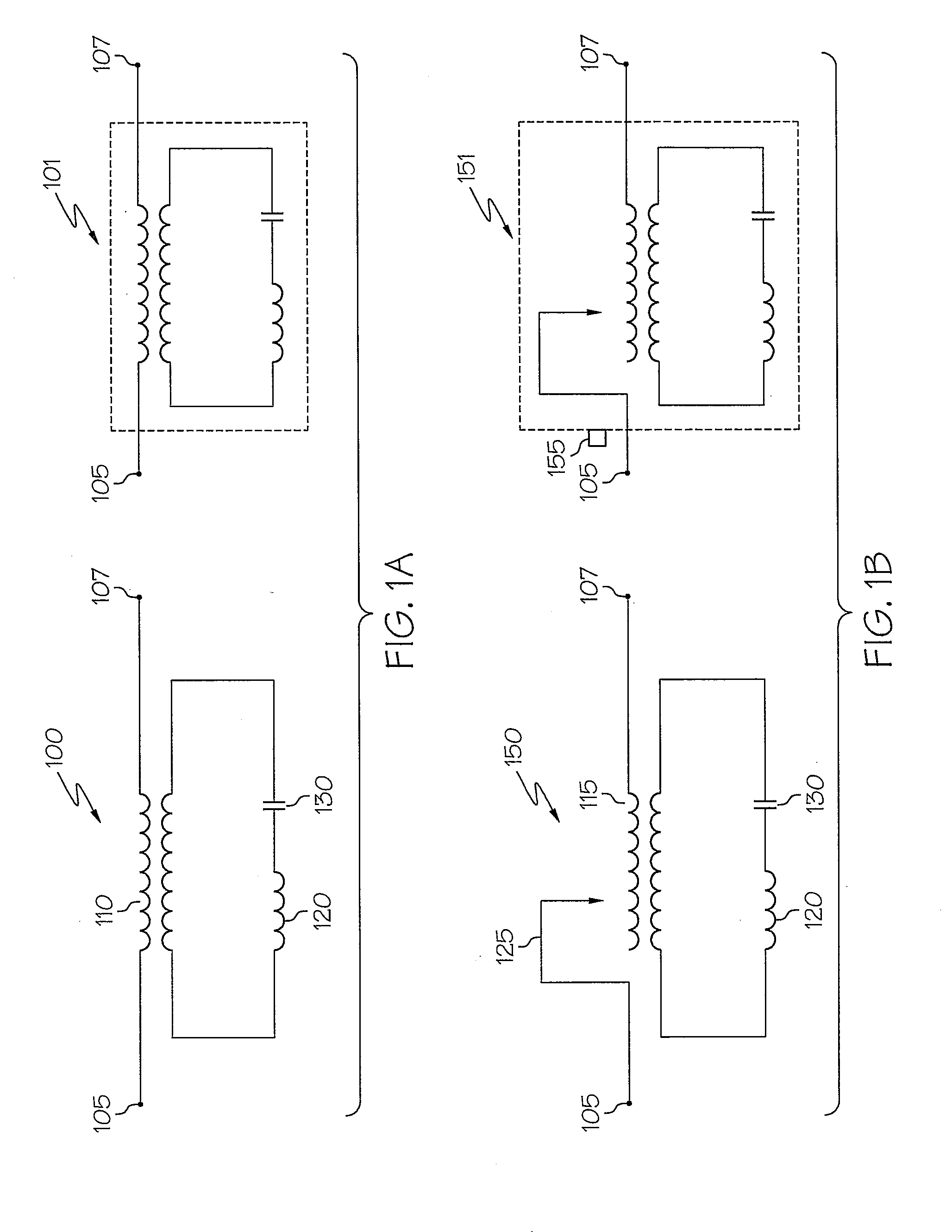
[0050]FIG. 1B illustrates the second embodiment depicting a first configuration of variable series impedance circuit 150 and series impedance device 151 (i.e., second or second-type series impedance circuit / device). As shown with the variable series impedance circuit / device 150 / 151, the current transformer 115 is a selectable / adjustable ratio transformer, which is constructed with an adjustable ratio mechanism 125 used for changing the effective ratio of the transformer. The adjustable ratio mechanism 125 is either manually adjustable (using adjustable ratio control 155) or automatically adjustable. As an example, the adjustable ratio mechanism 125 may be, but is not limited to, a bridging tap changer connected at a break in the transformer winding(s). The manually adjustable version of adjustable ratio mechanism 125 may incorporate a manual tap switch or a terminal board, while the automatically adjustable version of adjustable ratio mechanism 125 may incorporate a solid state swit...

third embodiment

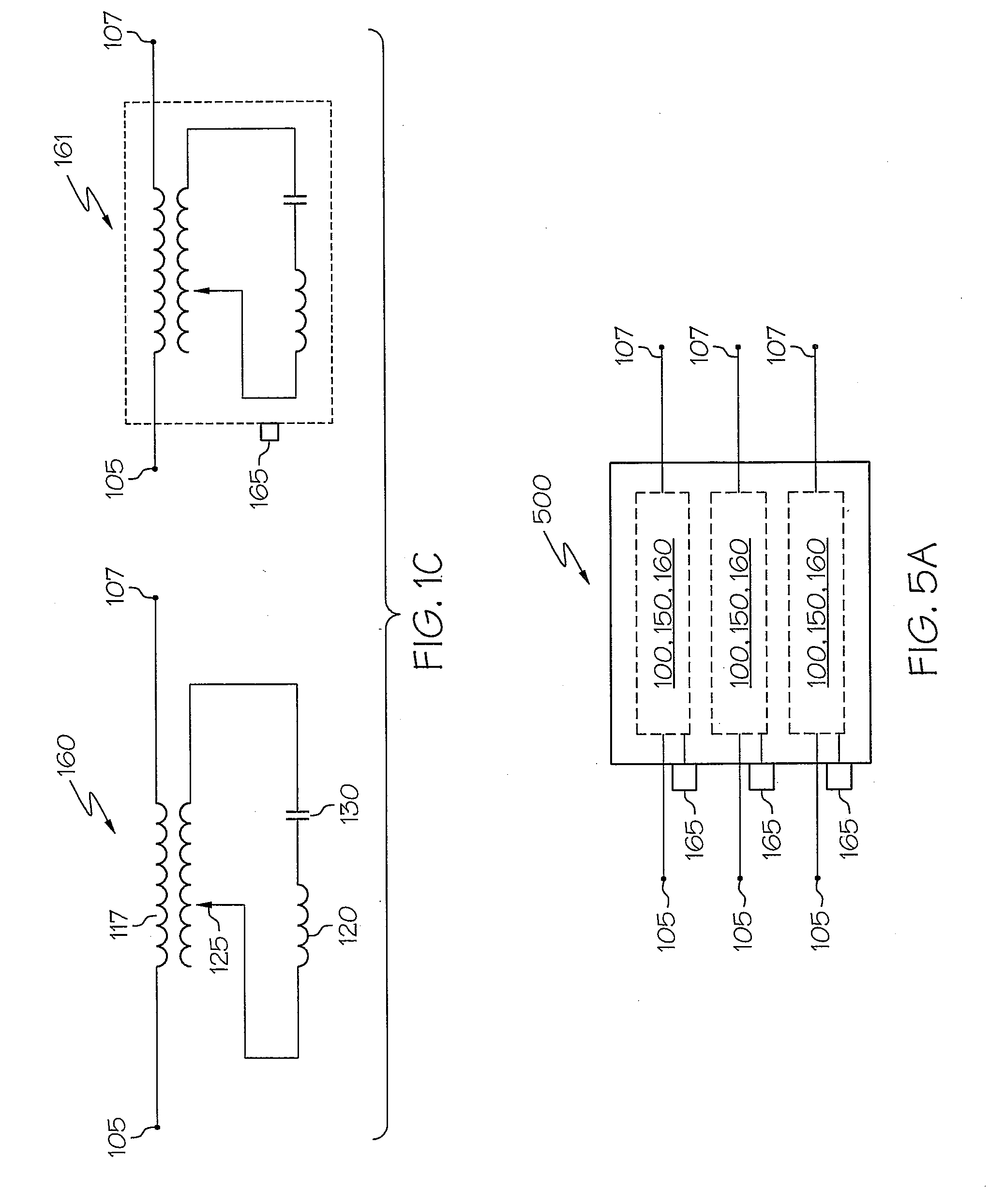
[0070]In a third embodiment in which the second windings are also tapped at corresponding points, the tap of the second winding of the first coil is electrically connected to the tap of the third winding of the second coil, the tap of the second winding of the second coil is electrically connected to the tap of the third winding of the third coil, and the tap of the second winding of the third coil is electrically connected to the tap of the third winding of the first coil. With this configuration, each of the first ends of the second windings is electrically connected to a separate one of the at least three input terminals.

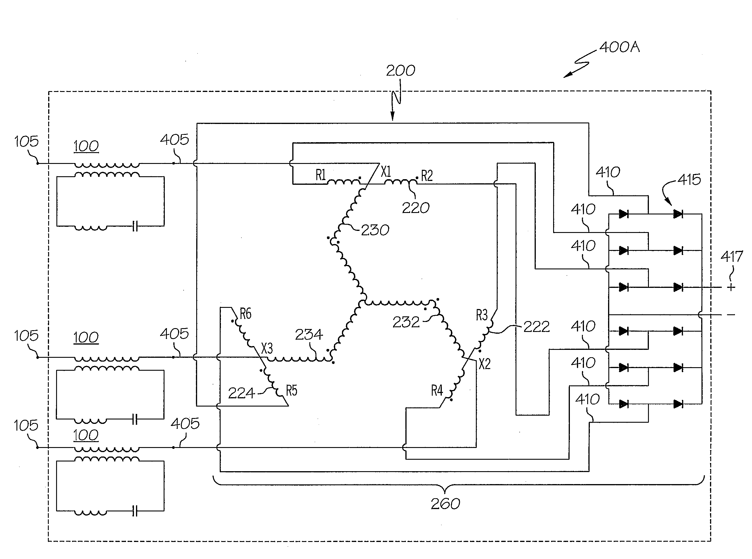
[0071]Thus, while the primary transformers described herein may be of any number of configurations / types of transformers; the illustrative embodiments provide zig-zag connected auto-transformers 200, which exhibit certain beneficial low harmonic characteristics to further complement the reduced harmonic effects of adding the series impedance circuits to the input...


PUM


Abstract

A method, device, and plurality of circuit enhancements for a rectifier system that enable reduction in lower order and higher order harmonics, without substantially reducing the rectifier's direct current output voltage. The rectifier system comprises a phase shifting primary transformer subsystem and a multi-pulse rectifier. At least one series impedance path is coupled to one of three input terminals/leads of the transformer subsystem and conducts one phase of three phase currents from a power supply to the transformer subsystem. The series impedance path provides low impedance to the 1st harmonic and substantially higher, inductive impedance to higher harmonics of the power supply frequency. The impedance of the series impedance path at a selected frequency above a third harmonic of the power supply's fundamental frequency divided by the impedance at the fundamental frequency of the three phase power supply is substantially greater than the selected frequency divided by the fundamental frequency of the power supply.

Description

PRIORITY CLAIM[0001]Benefit of priority under 35 U.S.C. §119(e) is claimed based on U.S. Provisional Application No. 61 / 042,466, entitled, “Low Harmonic Converter Circuit,” filed on Apr. 4, 2008, which disclosure is incorporated herein by reference.BACKGROUND OF THE INVENTION[0002]1. Technical Field[0003]This invention relates generally to electrical circuits and in particular to rectifier devices / systems comprising an electrical transformer coupled to a multiple pulse rectifier. Still more particularly, the present invention relates to electrical circuits and designs thereof for reducing harmonic currents with rectifier devices / systems.[0004]2. Description of the Related Art[0005]Multiple pulse rectifiers, such as 12-pulse rectifiers, typically exhibit less than ideal characteristics when connected to an output of a transformer. One major concern with such rectifier devices / systems (i.e., a transformer with output leads coupled to a multiple pulse rectifier) is the tendency for the...

Claims


Application Information

Patent Timeline
IPC IPC(8): H02M1/12
CPCH02M7/068H02M1/126
Inventor OWEN, DONALD W.
Owner HOWARD INDS
Why Eureka
Try Eureka