Fuel Assembly

a technology of fuel assembly and coolant, which is applied in the direction of nuclear engineering, greenhouse gas reduction, nuclear elements, etc., can solve the problems of reducing reactor power and increasing the coolant void in the core, and achieve the effect of suppressing the increase in the reactivity change rate during a hot-cold state change and increasing the negative void reactivity coefficien

Active Publication Date: 2009-10-08
HITACHI LTD
View PDF3 Cites 8 Cited by
  • Summary
  • Abstract
  • Description
  • Claims
  • Application Information

AI Technical Summary

Benefits of technology

[0009]To improve the economical efficiency of fuel at a low cost, it is necessary to expand the range of reactivity control with a minimum modification of equipments in the core. The inventors conducted various studies to achieve this improvement. As a result, the inventors found that since the void fraction in a boiling water reactor can be controlled, it is desirable to increase the negative void reactivity coefficient of the fuel assembly within a range that the stability of the core can be tolerated. The inventors also found that when the negative void reactivity coefficient increases, the rate of the reactivity change during a hot-cold state change of the fuel assembly must be the same as before so that a reactor shutdown margin is not reduced.
[0011]An object of the present invention is to provide fuel assemblies for which the increase in the reactivity change rate during its hot-cold state change can be suppressed and the negative void reactivity coefficient can be increased.
[0013]Since a second fuel rod is placed at corners of the outermost layer of a fuel rod array; other second fuel rods are placed, in the outermost layer, adjacent to the second fuel rod placed at the corner; and other second fuel rods are placed adjacent to a water rod, the increase in the reactivity change rate during its hot-cold state change can be suppressed and the negative void reactivity coefficient can be increased.
[0014]The above second fuel rods each include a plurality of third fuel rods having a burnable poison and a plurality of fourth fuel rods having a burnable poison; the first fuel rods are placed at corners of the outermost layer of a fuel rod array, the third fuel rods are placed adjacent to the first fuel rods placed at the corners in the outermost layer, and the fourth fuel rods are placed adjacent to the water rods; when the active fuel length of the fuel assembly is denoted L and a distance from the lower end of the active fuel length L in the axial direction of the fuel assembly is denoted h, and further when the active fuel length is divided into an upper region and a lower region at a position defined by h=L / 2, the third fuel rod placed adjacent to the first fuel rod placed at the corner in the outermost layer includes the burnable poison in most of the lower region and does not include the burnable poison in most of the upper region. This arrangement of the fuel rods also enables the above object to be achieved.
[0015]According to the present invention, the increase in the reactivity change rate during a hot-cold state change can be suppressed and the negative void reactivity coefficient can be increased.

Problems solved by technology

In the boiling water reactor, when the core flow rate is decreased during an operation, voids in the coolant in the core increase, lowering the reactor power.

Method used


Image

  • Fuel Assembly
  • Fuel Assembly
  • Fuel Assembly

Examples


first embodiment

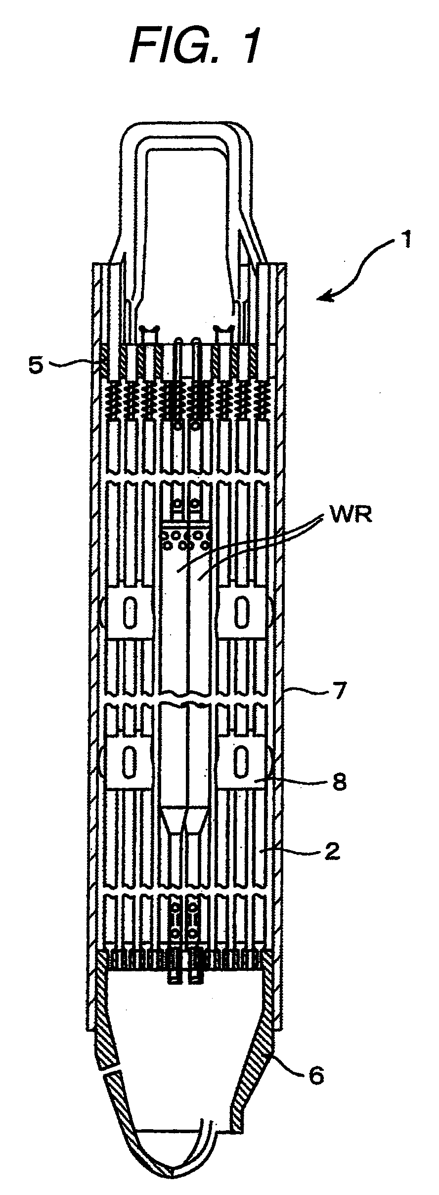
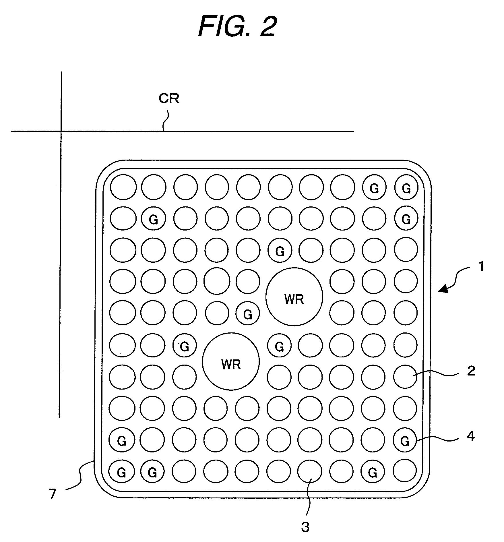
[0061]A fuel assembly in a first embodiment, which is a preferable embodiment of the present invention, will be described below in detail with reference to FIGS. 1 and 2, the fuel assembly being applied to a boiling water reactor.

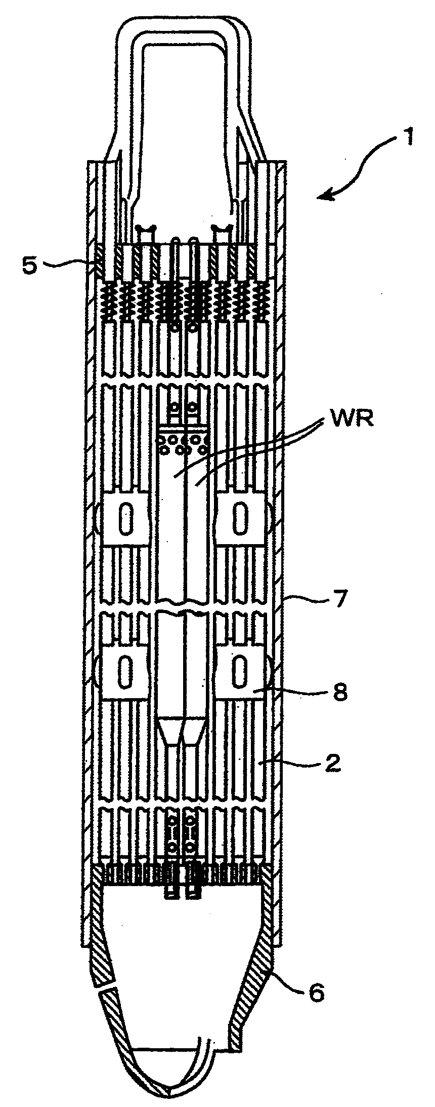
[0062]The fuel assembly 1 in this embodiment is provided with a plurality of fuel rods 2, an upper tie-plate 5, a lower tie-plate 6, a plurality of fuel spacers 8, a plurality of water rods WR, and a channel box 7. In each fuel rod 2, a plurality of fuel pellets (not shown) are loaded in a sealed cladding tube (not shown). The lower tie-plate 6 supports lower end portions of the fuel rods 2, and the upper tie-plate 5 holds upper end portions of the fuel rods 2. The fuel rods 2 are placed in 10 rows and 10 columns in the lateral cross section of the fuel assembly 1, as shown in FIG. 2. Two water rods WR, each of which occupies an region where four fuel rods 2 can be placed, are placed at the central part of the lateral cross section of the fuel assembly 1. L...

second embodiment

[0075]A fuel assembly in a second embodiment of the present invention will be described below with reference to FIG. 12, the fuel assembly being applied to a boiling water reactor. The fuel assembly 1A of this embodiment differs from the fuel assembly 1 in the first embodiment in that some of the plurality of uranium fuel rods 3 are replaced with partial-length fuel rods and the number of burnable poison-bearing fuel rods 4 and their placement are changed. Other construction of the fuel assembly 1A is the same as the fuel assembly 1. In this embodiment, the partial-length fuel rod includes uranium and does not include gadolinia. Its active fuel length is smaller than that of the uranium fuel rod 3. The fuel assembly 1A has 92 fuel rods 2. Of these, 67 fuel rods 2 are uranium fuel rods, 14 fuel rods 2 are partial-length fuel rods, and the remaining 11 fuel rods 2 are burnable poison-bearing fuel rods 4. The partial-length fuel rods are placed among uranium fuel rods 2 in a second lay...

third embodiment

[0078]A fuel assembly in a third embodiment of the present invention will be described below with reference to FIG. 13, the fuel assembly being applied to a boiling water reactor. The fuel assembly 1B of this embodiment differs from fuel assembly 1 in that two burnable poison-bearing fuel rods 4 adjacent to the water rods WR are placed at different positions. Other construction of fuel assembly 1B is the same as fuel assembly 1. The number of uranium fuel rods 3 and the number of burnable poison-bearing fuel rods 4 are the same as in the first embodiment.

[0079]As described above, the two burnable poison-bearing fuel rods 4 in the fuel assembly 1 are placed, in the third layer, adjacent to the water rods WR and nearer to the control rod CR than the two water rods WR. In this embodiment, the two burnable poison-bearing fuel rods 4 are placed, in the third layer, adjacent to the water rods WR and nearer to the third corner section.

[0080]In this embodiment, the negative void reactivity ...


PUM


Abstract

A fuel assembly, comprising:a plurality of first fuel rods including uranium and not including a burnable poison;a plurality of second fuel rods including said uranium and said burnable poison; anda water rod;wherein said second fuel rods are placed at corners of an outermost layer of a fuel rod array; other second fuel rods are placed, in said outermost layer, adjacent to said second fuel rods placed at said corners; and other second fuel rods are placed adjacent to said water rod.

Description

CLAIM OF PRIORITY[0001]The present application claims priority from Japanese Patent application serial no. 2007-322140, filed on Dec. 13, 2007 and Japanese Patent application serial no. 2008-087368, filed on Mar. 28, 2008, the content of which is hereby incorporated by reference into this application.BACKGROUND OF THE INVENTION[0002]The present invention relates to fuel assembly and, more particularly, to fuel assembly suitably used in a boiling water reactor.[0003]Many fuel assemblies including a fuel bundle, and a channel box being a rectangular parallelepiped cylinder and surrounding the fuel bundle, are loaded in the core of a boiling water reactor. Each fuel bundle is provided with a plurality of fuel rods sealed and having a plurality of fuel pellets including uranium, an upper tie-plate for supporting upper end portions of the fuel rods, a lower tie-plate for supporting lower end portions of the fuel rods, and fuel spacers for maintaining clearances among the fuel rods. The c...

Claims


Application Information

Patent Timeline
Patent Type & Authority Applications(United States)
IPC IPC(8): G21C3/32
CPCG21C3/326G21C3/328Y02E30/39Y02E30/38G21C7/04Y02E30/30
Inventor MITSUYASU, TAKESHIAOYAMA, MOTOOHINO, TETSUSHI
Owner HITACHI LTD
Why Eureka
Try Eureka