Beverage container

a beverage container and container body technology, applied in the field of beverage containers, can solve the problems of difficult for users or infants to drink beverage through straws, negative pressure within the container, and difficulty in drinking beverage through the straw. achieve the effect of drinking beverage easily

Active Publication Date: 2009-10-15
PIGEON CORP
View PDF5 Cites 44 Cited by
  • Summary
  • Abstract
  • Description
  • Claims
  • Application Information

AI Technical Summary

Benefits of technology

[0021]Therefore, an object of the present invention is to provide a beverage container that is capable of preventing a beverage contained in a container main body from leaking out even when a user tilts it to drink the beverage through a drinking spout part such as a straw, and preventing the container main body from generating negative pressure, to allow the user to drink the beverage easily.

Problems solved by technology

However, the problem of Patent Document 1 etc. is that the user has to operate the air hole control valve 6 by him / herself, which is a troublesome work.
However, the problem of Patent Document 1 to Patent Document 4 is that, although the beverage is prevented from leaking out when tilting the container to drink the beverage, the pressure within the container becomes negative as a user such as an infant drinks the beverage through the straw, making it gradually difficult for the user or infant to drink the beverage through the straw.

Method used


Image

  • Beverage container
  • Beverage container
  • Beverage container

Examples


first embodiment

[0109](The Entire Configuration Etc. of a Beverage Container 10)

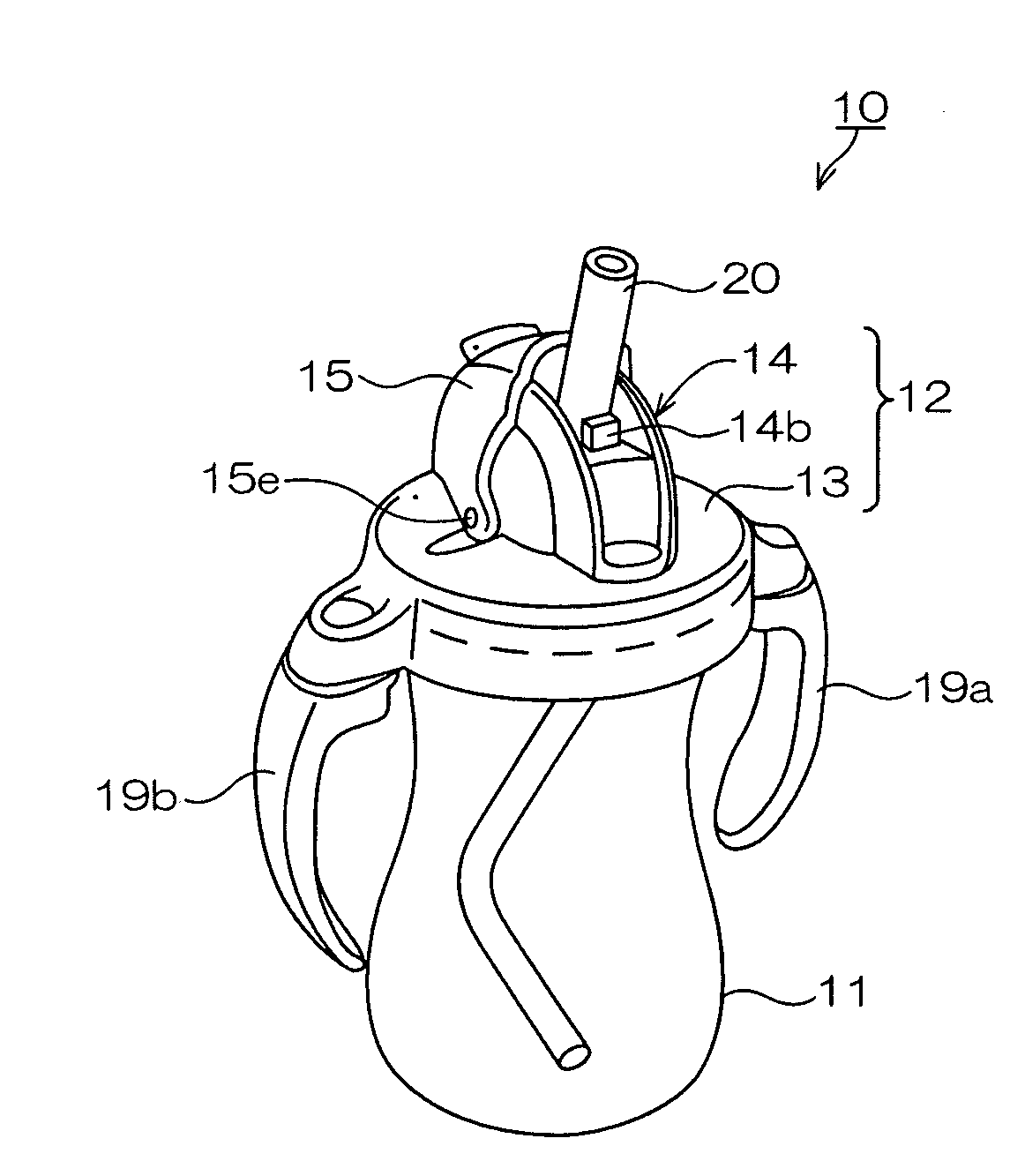
[0110]FIG. 1 is a schematic diagram of the beverage container 10 according to a first embodiment of the present invention and shows a drinking state. As shown in FIG. 1, the beverage container 10 has a clear container main body 11 for containing a liquid beverage, such as warm milk.

[0111]A base member 12 is disposed in the upper part of the container main body 11, and a straw 20, a drinking spout, is disposed in the base member 12. As shown in FIG. 1, the base member 12 has a base bottom part 13 that is disposed such as to cover the container main body 11, and a base upright part 14 that is formed such as to protrude above from the base bottom part 13.

[0112]The base member 12 also has a hood 15 which is a cap body for covering the upper part of the base upright part 14 openably.

[0113]As shown in FIG. 1, two handles 19a, 19b are disposed on each side of the base member 12 along the container main body 11.
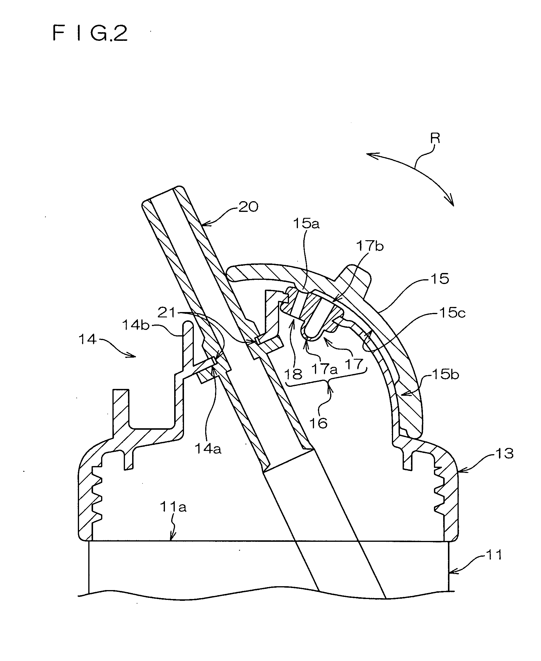
[0114]FIG. 2 is ...

second embodiment

[0170]FIG. 6 is a schematic perspective diagram showing a beverage container 30 according to a second embodiment of the present invention. The beverage container 30 according to this embodiment has the same configurations as the beverage container 10 of the first embodiment. Therefore, the descriptions of the same configurations etc. are omitted and only the differences between these beverage containers are described hereinafter.

[0171]As shown in FIG. 6, the beverage container 30 has a container main body 31 for containing a beverage, such as milk, and a base member 32 is disposed to cover an opening provided in the upper part of the container main body 31. The straw 20 through which the user can drink the milk contained in the container main body 31 is disposed in the base member 32.

[0172]A hood 35, for example, which is a hood member that houses or exposes the straw 20 as described hereinafter, is disposed in the base member 32.

[0173]The base member 32 also has disposed therein a ...

third embodiment

[0193]FIG. 10 is a schematic perspective diagram showing a beverage container 40 according to the third embodiment of the present invention. Because the beverage container 40 according to this embodiment has the same configuration as the beverage container 10 of the first embodiment, the descriptions of the same configurations etc. are omitted and only the differences between these beverage containers are described hereinafter.

[0194]The beverage container 40 has a container main body 41 for containing a beverage such as milk, and a base member 42 is disposed to cover an opening provided in the upper part of the container main body 41.

[0195]Two handles 49a, 49b are disposed on each side of the base member 42 along the container main body 41.

[0196]Also, a drinking spout 50 and a straw 50a are disposed in the base member 42. A hood 45 is disposed in the base member 42 to cover the drinking spout 50, wherein an inner surface of the hood 45 covers and closes a leading end of the straw 50...


PUM


Abstract

The disclosed subject matter provides a beverage container configured to prevent a beverage from leaking out even when a user tilts the container, and allows the user to easily drink the beverage even when pressure within the container is negative. The beverage container can include a container main body, a base member, and a cap body. The base member can have first ventilation means for regulating a pressure variation in the container main body, and second ventilation means for introducing air from the outside when the pressure within the container main body becomes negative in relation to the outside pressure and capable of preventing leakage of a liquid beverage contained in the container main body. The cap body can include ventilation open/close means and the like capable of changing the state of the first ventilation means to a ventilation state or a closed state. The ventilation open/close means can be configured to bring the first ventilation means into the closed state when in a portable state such as when the user carries the beverage container, and to bring the first ventilation means into the ventilation state when in an operating state.

Description

TECHNICAL FIELD[0001]The present invention relates to a beverage container for containing a beverage such as milk.BACKGROUND[0002]A beverage container having a straw at a drinking spout has been used as a conventional beverage container from which an infant, for example, can drink milk, tea such as barley tea, juice and other kind of beverage. This type of beverage container has a cap so that it is portable, and another advantage thereof is that the infant can drink the beverage easily through the straw.[0003]Such a beverage container is also so configured that the straw can be sealed so that the beverage within the container does not leak from the straw when a user carries it in a bag etc.[0004]Moreover, when warm milk etc. is contained in this beverage container and the straw is sealed, positive pressure is generated within the container, and, as a result, the warm milk might squirt out of the straw when the infant actually opens the straw to drink the warm milk.[0005]As described...

Claims


Application Information

Patent Timeline
Patent Type & Authority Applications(United States)
IPC IPC(8): A47G19/22B65D25/00
CPCA47G19/2266B65D25/40B65D47/06B65D47/32
Inventor YAMASHITA, DAISUKEOUSHI, YOSHIYUKI
Owner PIGEON CORP
Why Eureka
Try Eureka