
Convection Barrier

a technology of convection barrier and seal, which is applied in the field of convection barrier, can solve the problems of unfavorable temperature rise of stored samples, inability to arrange robots in a 80° c. environment, and standard handling devices such as robots, which are not usually used properly, so as to improve the seal of the interior of the freezer, simplify the process of opening and closing the flap, and improve the friction coefficient of the material

Inactive Publication Date: 2010-02-11
F HOFFMANN LA ROCHE & CO AG
View PDF27 Cites 1 Cited by
  • Summary
  • Abstract
  • Description
  • Claims
  • Application Information

AI Technical Summary

Benefits of technology

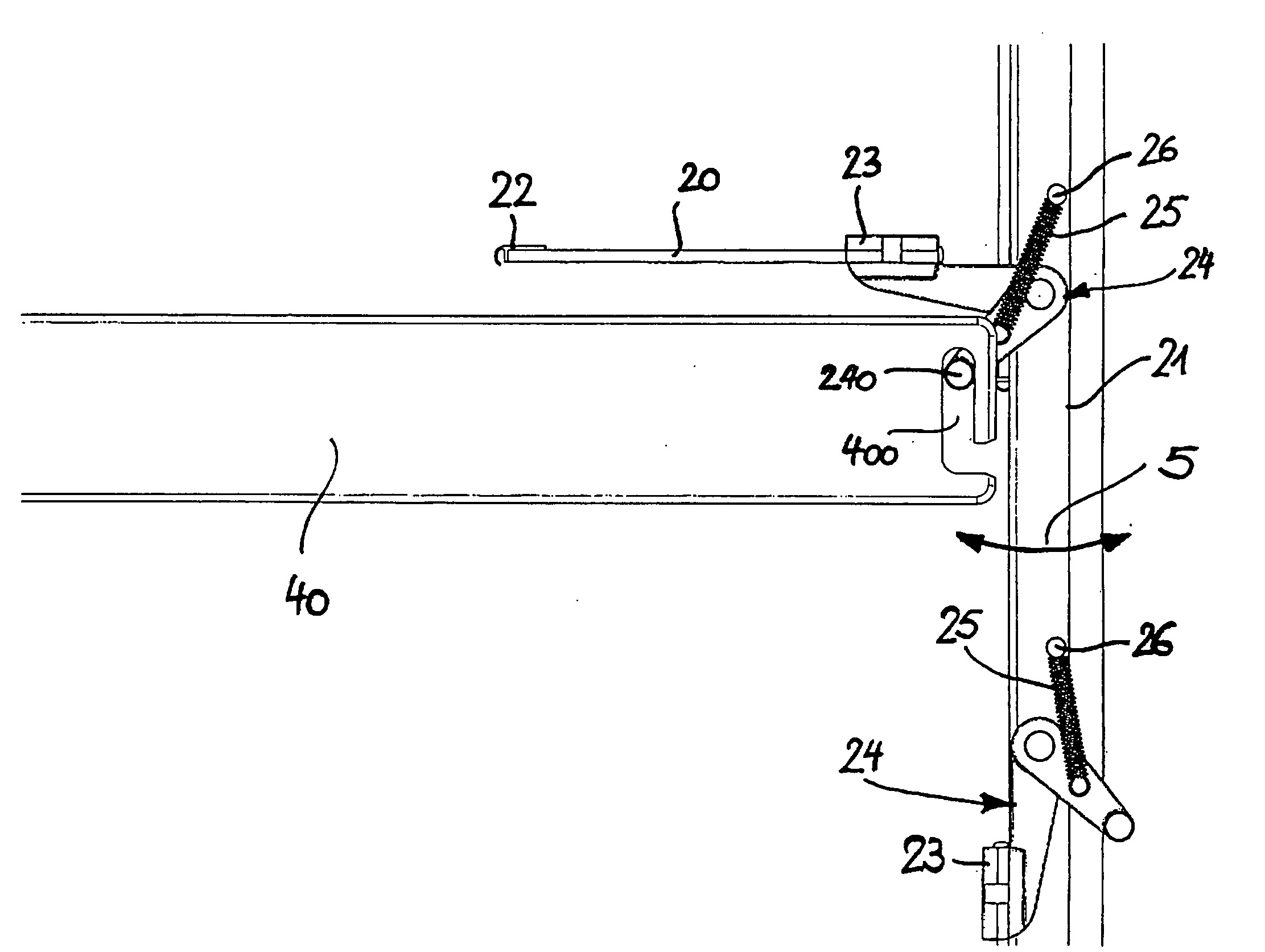
[0014]In some embodiments, the curtain formed by the individual flaps covers the opening which allows access to the freezer, so that the −80° C. air may not flow out of the freezer as the door of the freezer is open. On the other hand, it must also be possible to get access to the desired sample or samples stored in the interior of the freezer. This can be achieved according to some embodiments, by allowing an actuator (such as a robot or a part thereof) to open an individual flap so as to generate a row-like opening to the interior of the freezer. Depending on where the sample to be accessed is stored in the interior of the freezer, only one of the flaps need be opened so as to allow the robot to get access to the sample. Thus, outflow of −80° C. air from the interior of the freezer and inflow of −20° C. air to the interior of the freezer is prevented or at least greatly reduced. Accordingly, the above-identified disadvantages of temperature rise in the interior of the freezer, generation of negative pressure making the door of the freezer extremely difficult to open, etc., may be prevented or at least greatly reduced.
[0017]In some further embodiments of the convection barrier according to the invention, at least on the edges abutting or overlapping the adjacently arranged flap, lips are attached to the individual flaps. Preferably, a lip is attached to at least one of the edges abutting or overlapping the adjacently arranged flap. Such lips may serve a plurality of purposes. First, the lips further improve the seal of the interior of the freezer. Second, they form protection for the material the flaps are made of. And third, they simplify the process of opening and closing the flap, since the frictional coefficient of the material the lips are made of is low. A particularly suitable material for the lips is Teflon(& (polytetrafluoroethylene).
[0018]In some embodiments of the convection barrier according to the invention, the individual flaps are made of glass ceramics. Glass ceramics is a material which has a low thermal conductivity. Thus, the interior of the freezer is additionally protected against the comparatively “high” temperatures (−20° C.) outside the interior of the freezer (where the temperature is about −80° C.). Since the glass ceramics has a very small thermal expansion coefficient, the temperature gradient perpendicular to the flaps does not cause bending of the flaps which could give rise to a leakage between adjacent flaps.

Problems solved by technology

However, this system has some disadvantages.
Upon opening an individual drawer by pulling the said drawer outwardly, this does inherently bear the risk that an adjacently arranged drawer is also pulled out although this is not intended and may cause an unwanted temperature rise of the stored samples.
However, at said temperatures standard handling devices, such as for example robots, usually do not work properly.
As mentioned above, the robot cannot be arranged in a −80° C. environment, since this simply is not economically feasible in such an environment, and in addition, maintenance of the robot would be difficult then.
However, particularly with conventional upright standing freezers, certain problems may arise.
Firstly, upon having opened the door in order to allow the robot to access the interior of the freezer, the −80° C. cooled air flows out of the interior of the freezer while at the same time −20° C. air flows from the environment into the interior of the freezer thus leading to a rise in temperature and humidity within the freezer.
Secondly, opening and closing of the door results in a negative pressure inside the freezer which makes the door extremely difficult to get opened again until the negative pressure is equalized by inflowing air, e.g. through the sealing of the door of the freezer or through a pressure equilibration valve in the wall of the freezer.
This usually takes a considerable period of time which may amount up to 30 minutes, for example.
In addition, the cooling down of the −20° C. air which is more humid than the −80° C. air results in formation of ice within the freezer.

Method used


Image

  • Convection Barrier
  • Convection Barrier
  • Convection Barrier

Examples


Embodiment Construction

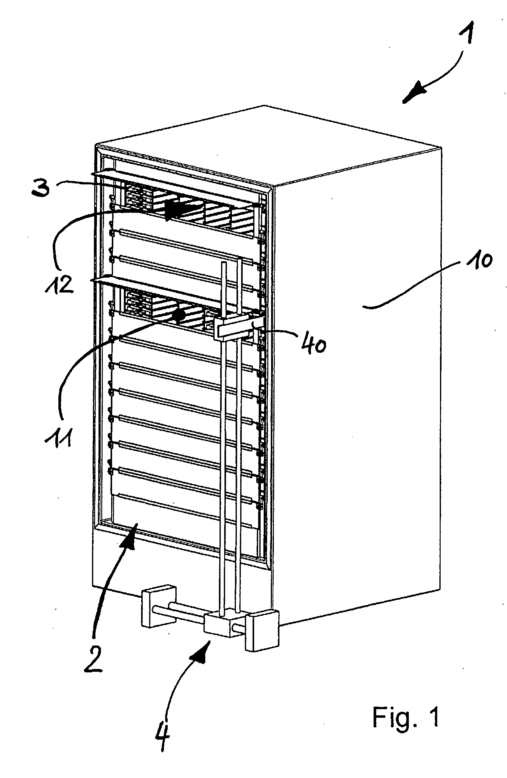
[0025]FIG. 1 shows a perspective view of an embodiment of a freezer 1 according to the invention with an embodiment of a convection barrier 2 according to the invention mounted thereto, with the door of the freezer not being shown in FIG. 1 for the sake of simplicity. Freezer 1 comprises a housing 10 having an opening 11 at the front side of freezer 1. A plurality of compartments are arranged in the interior 12 of freezer 1, in which drawers 3 carrying trays containing the stored samples can be arranged. Also shown schematically in FIG. 1 are parts of a robot 4 for automated access to the samples, in particular an actuator 40 for opening and closing the flaps of the convection barrier 2.

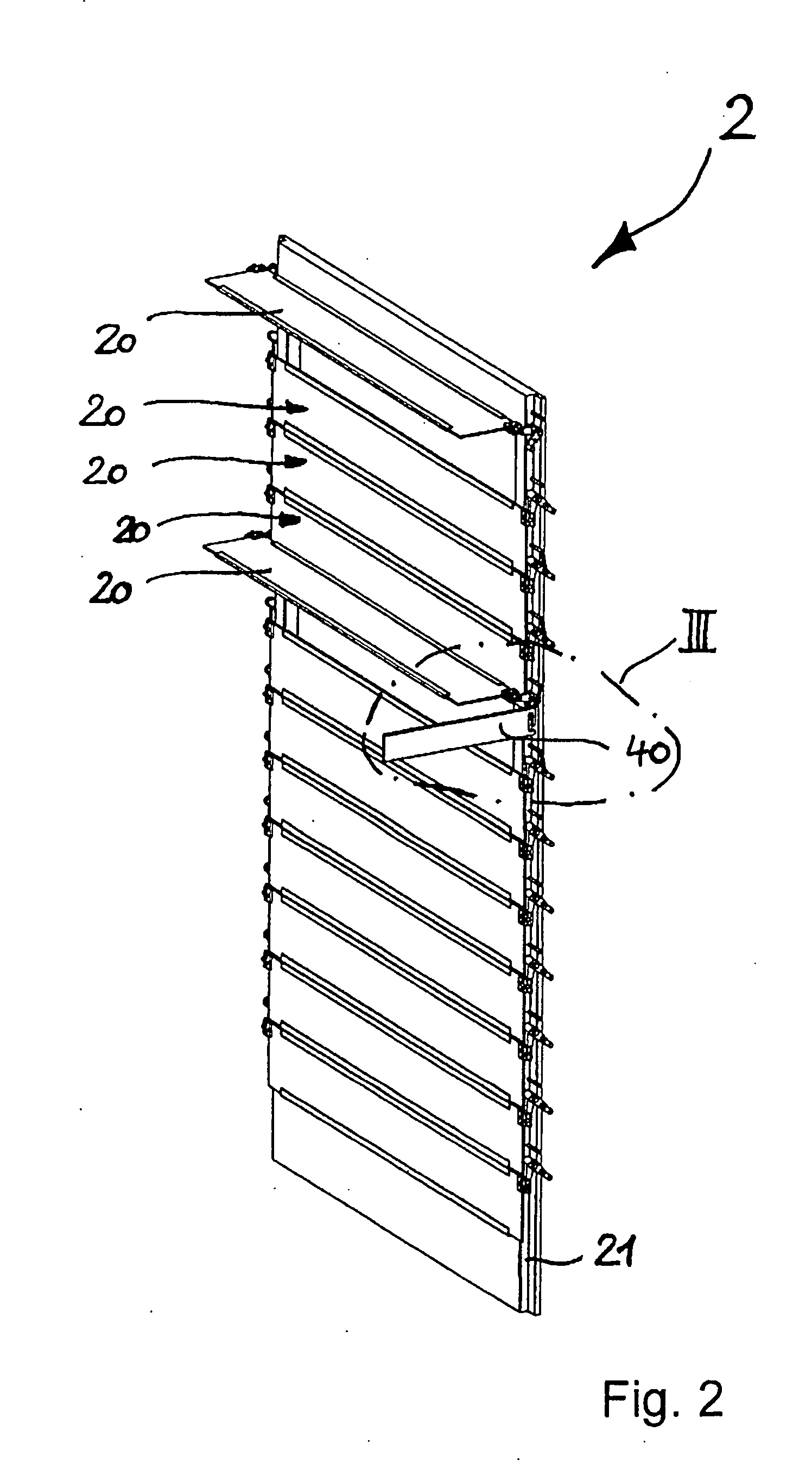
[0026]The embodiment of the convection barrier 2 according to the invention shown in FIG. 1 mounted to freezer 1 is shown in FIG. 2 prior to being mounted to freezer 1. Convection barrier 2 comprises a plurality of individual flaps 20 mounted to an outer frame 21, with flaps 20 being adjacently and a...


PUM


Abstract

Embodiments of the present invention include a convection barrier for a freezer which may comprise a plurality of individual flaps arranged one above the other in a manner such as to be capable of forming a closed curtain of individual flaps, with each individual flap extending over a predetermined width corresponding at least to the width of the interior of the freezer and being pivotable between a closed position and an open position so as to allow access to the interior of the freezer when the flap is in the open position. Embodiments may also include actuation means attached to the individual flaps for allowing an actuator to engage the actuation means of an individual flap so as to pivot the said flap between the closed position and the open position.

Description

CROSS-REFERENCE TO RELATED APPLICATIONS[0001]The present application claims priority to European Patent Application No. 08161793.8, filed Aug. 5, 2008, the entire contents of which are herein incorporated by reference in its entirety.FIELD OF THE INVENTION[0002]The present invention relates to a convection barrier as well as a freezer comprising such convection barrier.BACKGROUND[0003]In clinical studies a wide variety of assays can be carried out to answer questions related to diagnosis (e.g. biomarker), treatment (e.g. efficacy of a drug) and prevention of diseases.[0004]Large sample collections of biological samples can be established e.g., within the context of clinical studies. Such biological samples can be, e.g., blood samples (whole blood, plasma, serum), urine samples, tissue samples, or samples containing cells (e.g. primary cells, stem cells), proteins, DNA, RNA (RNAi, mRNA), or antibodies.[0005]An automated facility for storing biological samples at −80° C. is used in th...

Claims


Application Information

Patent Timeline
Patent Type & Authority Applications(United States)
IPC IPC(8): F25D23/00F25D23/02
CPCF25D11/04F25D25/04F25D23/025F25D13/02
Inventor ZUMSTEIN, THOMASFATTINGER, CHRISTOFVOEGELIN, DIETER
Owner F HOFFMANN LA ROCHE & CO AG
Learn More