Bearing assembly, motor and recording disk drive

a technology of bearing assembly and motor, which is applied in the direction of sliding contact bearings, mechanical equipment, mechanical energy handling, etc., can solve the problems of affecting the reading and writing of information from and on the recording disk, the life of the bearing assembly, and the inability to supply lubrication oil to all portions of the dynamic pressure groove, so as to prevent the generation of air bubbles

Active Publication Date: 2010-02-02
NIDEC CORP
View PDF18 Cites 1 Cited by
  • Summary
  • Abstract
  • Description
  • Claims
  • Application Information

AI Technical Summary

Benefits of technology

[0009]In order to overcome the problems described above, preferred embodiments of the present invention minimize generation of negative pressure in a thrust dynamic pressure bearing mechanism of an electric motor, thereby preventing the generation of air bubbles in a lubrication oil.
[0011]With this structure, during relative rotation, the dynamic pressure grooves in the thrust dynamic pressure bearing and the through hole are superposed sequentially. Therefore, a sufficient amount of the lubrication oil can be supplied to the ends of the thrust dynamic pressure grooves, and it is possible to reliably prevent local generation of a negative pressure and generation of air bubbles in the lubrication oil. It is more preferable that an opening end of the through hole be superposed on a radially outer end of the thrust dynamic pressure groove.
[0012]According to the present preferred embodiment, since the through hole rotates with respect to the thrust dynamic pressure groove, it is possible to efficiently minimize generation of the negative pressure in the thrust dynamic pressure bearing mechanism, thus preventing generation of air bubbles in the lubrication oil. Moreover, the inflow amount of the lubrication oil into the thrust dynamic pressure bearing mechanism from the outer peripheral side thereof can be increased. Therefore, generation of the negative pressure can be further minimized.

Problems solved by technology

The air bubbles cause troubles such as NRRO (Non Repeatable Run Out) due to abnormal vibration when the motor rotates, thus adversely affecting reading and writing of information from and on a recording disk and a lifetime of the bearing assembly.
Therefore, generation of the negative pressure can be minimized in a certain dynamic pressure groove, but it is not possible to supply the lubrication oil to all portions of the dynamic pressure grooves at which the negative pressure is generated.

Method used


Image

  • Bearing assembly, motor and recording disk drive
  • Bearing assembly, motor and recording disk drive
  • Bearing assembly, motor and recording disk drive

Examples


first preferred embodiment

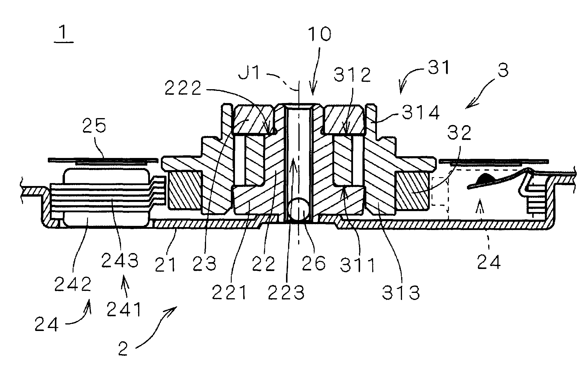
[0025]FIG. 1 shows an internal structure of a recording disk drive 60 including an electric spindle motor 1 (hereinafter referred to as “motor 1”) according to a first preferred embodiment of the present invention. The recording disk drive 60 is a hard disk drive, and includes a recording disk 62 in the form of a circular disk on which information can be recorded, an access section 63 which reads and / or writes information from and on the recording disk 62, the electric motor 1 which holds and rotates the recording disk 62, and a housing 61 having an internal space 110 which accommodates the recording disk 62, the access section 63, and the motor 1.

[0026]As shown in FIG. 1, the housing 61 includes a box-like first housing member 611 provided at its upper portion with an opening. The first housing member 611 does not have a lid. The motor 1 and the access section 63 are mounted on a bottom in the first housing member 611. The housing 61 also includes a plate-like second housing member...

second preferred embodiment

[0054]FIG. 9 is a vertical cross-sectional view of a motor 1a according to a second preferred embodiment of the present invention. Components in this preferred embodiment having the same functions as those of the first preferred embodiment are designated with the same names and reference numerals even if they have different shapes from those of the first preferred embodiment. The motor 1a is used for rotating the recording disk 62 shown in FIG. 1 like the motor 1 shown in FIG. 4. Except for the shapes of the sleeve member 31 and the ring member 23, the motor 1a has the same structure as that of the motor 1. The same structures are labeled with the same reference numerals.

[0055]In the motor 1a, like the motor 1, herringbone grooves 316 functioning as radial dynamic pressure grooves are formed in an inner peripheral surface of a sleeve member 31, and a radial dynamic pressure bearing mechanism 410 is formed in a side gap 41 between an outer peripheral surface of a shaft 22 and an inne...

third preferred embodiment

[0060]The shape of the through hole 318 of the motor 1a is not limited to a straight and an inclined shape. For example, the through hole 318 can be formed by connecting a hole horizontally extending from an upper portion of the radial dynamic pressure bearing mechanism 410 and a hole vertically extending from the thrust dynamic pressure bearing mechanism 420 to each other, as shown in FIG. 10.

[0061]Also in this preferred embodiment, the same effects as those obtained by the first and second preferred embodiments can be obtained.

Other Preferred Embodiments

[0062]Although exemplary preferred embodiments of the present invention have been explained above, the present invention is not limited to the above. The present invention can be modified in various ways.

[0063]In each of the aforementioned motors 1 and 1a, preferably the shaft 22 is fixed to the base plate 21 and the sleeve member 31 rotates with respect to the flange portion 221 of the shaft 22. However, a structure may be used in...


PUM


Abstract

A bearing assembly for use in an electric motor minimizes the generation of a negative pressure. In the bearing assembly, gaps are formed between a shaft provided with a flange portion, a ring member mounted on the shaft, and a sleeve member with a through hole formed therein are continuously filled with lubrication oil. When a rotor rotates, the rotor is supported by a fluid dynamic pressure. In the bearing assembly, herringbone grooves are formed in an upper surface of the flange portion of the shaft fixed to a base plate. When the sleeve member rotates with respect to the shaft, ends of all of the herringbone grooves and the through hole are superposed on each other sequentially. Thus, the lubrication oil can be efficiently supplied to an outer peripheral region in the thrust dynamic pressure bearing mechanism in which the negative pressure is most prone to be generated, and generation of the negative pressure can be efficiently minimized.

Description

BACKGROUND OF THE INVENTION[0001]1. Field of Invention[0002]The present invention relates to a bearing assembly utilizing a fluid dynamic pressure provided in a motor.[0003]2. Description of the Related Art[0004]A recording disk drive such as a hard disk drive includes a spindle motor (hereinafter referred to as “motor”) for rotating a recording disk. The motor uses a bearing assembly utilizing a fluid dynamic pressure. In many cases in the bearing assembly, a thrust dynamic pressure bearing mechanism and a radial dynamic pressure bearing mechanism are provided between a shaft or a component of the bearing assembly connected to the shaft and a sleeve into which the shaft is inserted.[0005]The structure of an exemplary known bearing assembly includes an inner sleeve and an outer sleeve combined to form a sleeve, and a shaft is inserted into the sleeve. A radial bearing is formed between an outer peripheral surface of the shaft and an inner peripheral surface of the inner sleeve. Thru...

Claims


Application Information

Patent Timeline
Patent Type & Authority Patents(United States)
IPC IPC(8): F16C32/06
CPCF16C17/026F16C17/107F16C33/103F16C33/107
Inventor FENG, MINGSODEOKA, SATORU
Owner NIDEC CORP
Why Eureka
Try Eureka