Protective cap for dispensers and container comprising said cap

a dispenser and protective cap technology, applied in the direction of instruments, volume meters, single-unit devices, etc., can solve the problems of easy misplacement, unsuitable operation in situations of restricted freedom of movement, and complex articulated mechanisms able to achieve the locking of the plunger. achieve the effect of simple manner

Active Publication Date: 2009-10-15
APTAR ITAL
View PDF10 Cites 23 Cited by
  • Summary
  • Abstract
  • Description
  • Claims
  • Application Information

AI Technical Summary

Benefits of technology

[0011]Moreover, an object of the invention is to make available a protective cap for dispensers that can be operated in a very simple manner and hence even in hardship situations.

Problems solved by technology

Containers of this type, described for example in EP Patent 952892, have the drawback of requiring complex articulated mechanisms able to achieve the locking of the plunger of the dispenser as a result of the rotation of the actuator member.
Hence, they are unsuitable to be operated in situations of constrained freedom of movement, e.g. when the user has one hand busy as is often the case whilst driving a vehicle, whilst writing or in other similar situations.
These hoods, widely used, have the drawback of remaining uncoupled from the container during the dispensing operation and hence they can easily be misplaced.
Hence, they too are unsuitable to be operated in situations of constrained freedom of movement for the user.
Disadvantageously, this cap is therefore not applicable to dispensers having a plunger for dispensing a liquid under pressure.
Disadvantageously, the complexity of this dispenser requires complex operations for mounting it on the respective container, linked mostly to the need to align the lid with a respective hinging portion of the container.
Moreover, the plunger is able to dispense the product along its translation direction, whilst the dispenser does not seem suited to dispense the product in all directions, e.g. a horizontal direction.

Method used


Image

  • Protective cap for dispensers and container comprising said cap
  • Protective cap for dispensers and container comprising said cap
  • Protective cap for dispensers and container comprising said cap

Examples


Embodiment Construction

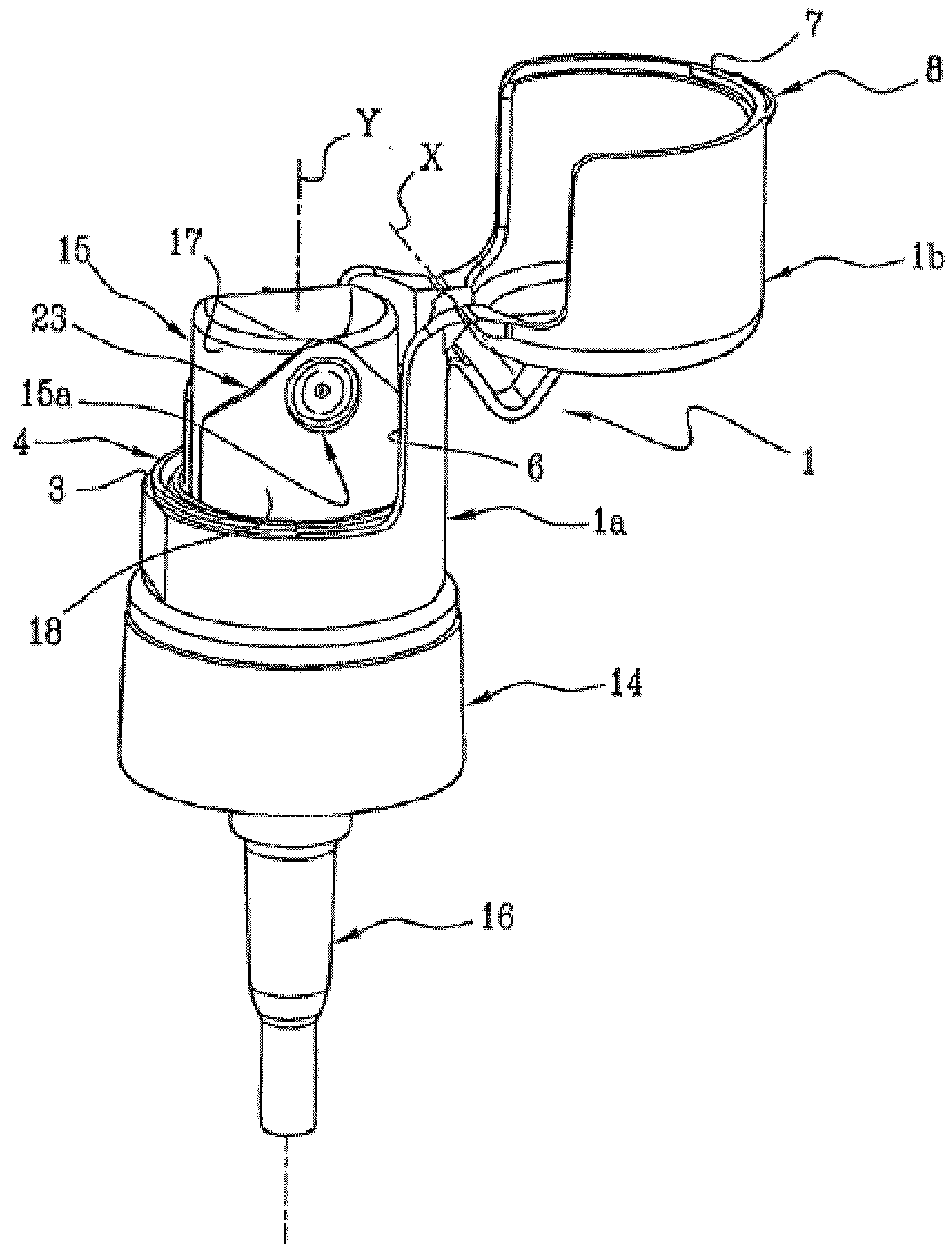
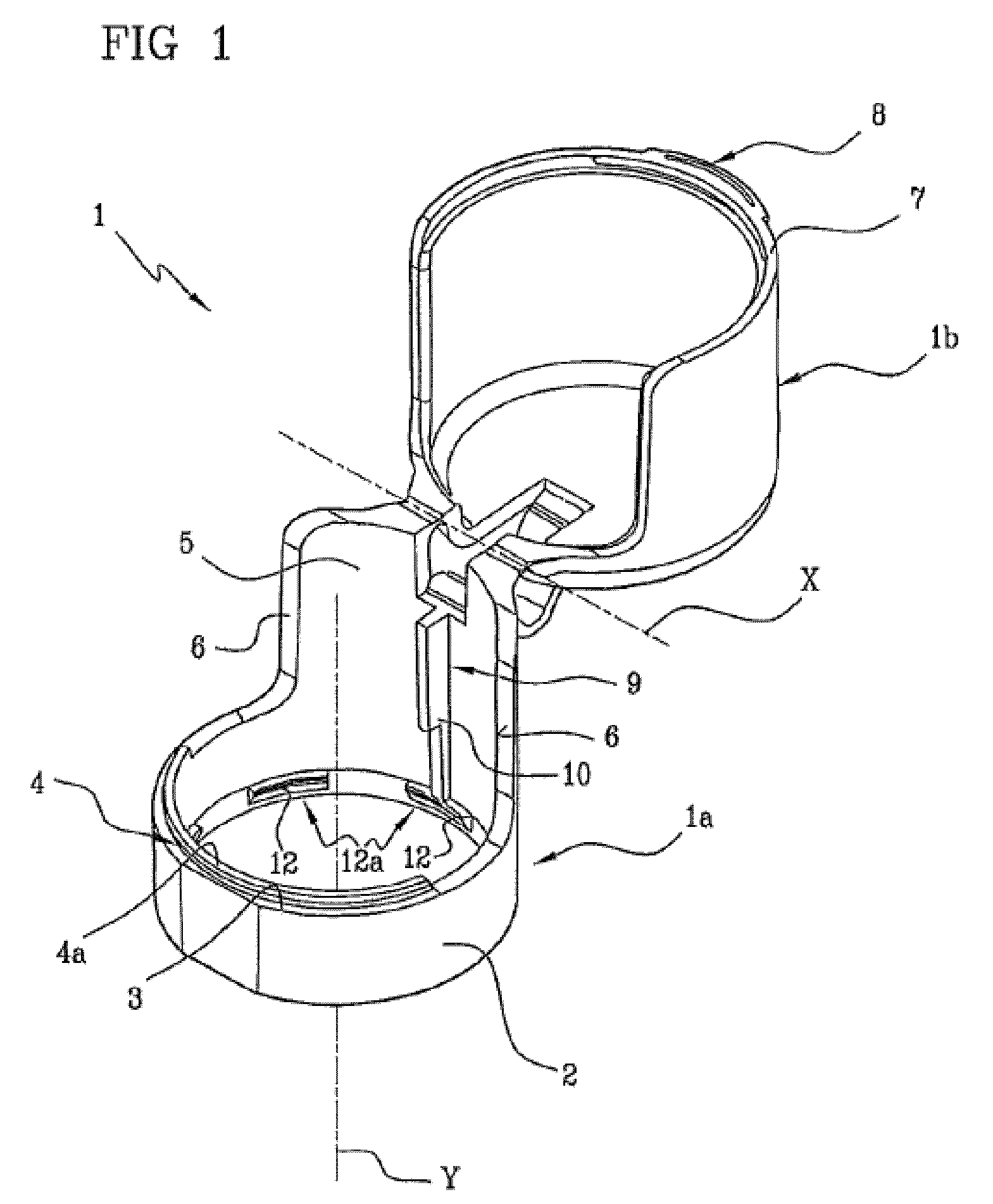
[0020]In accordance with the accompanying figures, the reference number 1 indicates a protective cap for dispensers according to the present invention.

[0021]The cap 1 comprises a base portion 1a and a lid 1b hinged to the base portion 1a to rotate around an axis of rotation “X”. In particular, the lid 1b is movable between a closed position, in which it abuts the base portion 1a to close a space internal to the cap 1, and an open position in which it is rotated to allow access to the space internal to the cap 1.

[0022]The base portion 1a comprises a cylindrical body 2 that develops around an axis “Y” and has substantially axial-symmetrical conformation relative to said axis “Y”. The cylindrical body 2 presents an abutment surface 3 having a planar or substantially planar lay, which can be abutted by the lid 1b when the latter is in the closed position. The abutment surface 3 is equipped with coupling means 4 stably engageable by a corresponding portion of the lid 1b to keep the lid 1...


PUM

PropertyMeasurementUnit
pressureaaaaaaaaaa
radial dimensionaaaaaaaaaa
areaaaaaaaaaaa

Abstract

A container comprises a dispensing head (13) and a protective cap (1) fitted on the dispensing head (13). The cap (1) comprises a base portion (1a) engageable to a dispensing head (13); a lid (1b) hinged to said base portion (1a) and movable between an open position, in which it allows access to the dispensing head (13), and a closed position in which it prevents access to the dispensing head (13); an outer locator plate (9) engageable with a corresponding inner locator plate (24) of said dispensing head (13), the mutual engagement between said locator plates (9, 24) defining a screwing motion of the cap (1) relative to the dispensing head (13) to automatically achieve an installation of the cap (1) on the dispensing head (13) according to a pre-determined mutual angular positioning. The dispensing head (13) comprising a base (14) able to be coupled stably to an outlet portion of the container; a dispenser (15) having a dispensing head and slidably movable relative to the base (14) to obtain a dispensing of a product contained in the container as a result of a pressure exerted on the dispenser (15); at least one inner locator plate (24) engageable with the outer locator plate (9) of the cap (1), to guide the outer locator plate (9) according to a helical path around the dispenser (15).

Description

BACKGROUND OF THE INVENTION[0001]The present invention relates to a protective cap for dispensers. More in particular, the present invention relates to a protective cap for dispensers of liquids under pressure such as atomisers, micro-pumps or similar devices with a pressure-operated plunger. By way of example, dispensers of the type described above are applied to containers of perfumes, lotions, detergents or cosmetics in general.[0002]The invention further relates to a container containing said cap.[0003]Currently known are containers lacking a cap and provided with a spray dispenser in which the dispenser can be brought to assume a blocking position by rotating an external actuating element around a longitudinal axis of the container. Containers of this type, described for example in EP Patent 952892, have the drawback of requiring complex articulated mechanisms able to achieve the locking of the plunger of the dispenser as a result of the rotation of the actuator member. Moreove...

Claims


Application Information

Patent Timeline
Patent Type & Authority Applications(United States)
IPC IPC(8): B65D88/54B65D47/00
CPCB05B11/30B05B11/0008Y10T29/49899B05B11/0032B05B11/10
Inventor SANTONI, GIORGIOCAMPLONE, FABRIZIO
Owner APTAR ITAL
Why Eureka
Try Eureka