System and method of RFID wireless control

a wireless control and wireless control technology, applied in the field of wireless control system and method, can solve the problems of increasing construction difficulty and construction cost, unable to carry out the function of remote control with original conduits, and difficulty in adding extra switches, so as to facilitate the daily life of disabled or elderly people, and the system is more secure in us

Inactive Publication Date: 2009-10-15
HSIAO JUE HSUAN +1
View PDF7 Cites 176 Cited by
  • Summary
  • Abstract
  • Description
  • Claims
  • Application Information

AI Technical Summary

Benefits of technology

[0008]A wireless remote control system of the present invention mainly uses a universal unique product labeling technique (for example, RFID) as device identification codes for respective identification of control for appliances or apparatuses. The RFID method for identification is universally unique (no duplicate), and identification codes can be read easily and conveniently under no-contact operation.
[0012]According to a wireless control system of the present invention, each electronic device can be one-to-one controlled through the specified control unit, while the electronic devices can be one-to-many controlled by the controller. Thus, construction of a huge and complex conduit system of mechanical switches can be avoided, so as to save time and costs. Meanwhile, if extra electronic devices are added, the present invention can also save a rearrangement of the conduit system which ruins the appearance of the building or causes inconvenience in daily life; an additional cost for decoration required for cover the system.
[0013]A wireless control system of the present invention can transmit radio waves for communication on the industrial, scientific and medical (ISM) bands, and hence it has the advantage of better electromagnetic penetration, so that the locations of the electronic devices, the specified control unit and the controller are more flexible, and this makes it easier to carry out control.
[0015]The wireless control system or method of the present invention can be used to construct a remote control system for common home appliances to facilitate daily life of disabled or elderly persons. The present invention also allows schools, organizations or malls to quickly construct a remote control system for illumination and power. Besides facilitating centralized control and construction maintenance, it can further utilize a programmable control procedure function, so that the system is more secure in use.

Problems solved by technology

Once conduits are installed firmly, it is difficult to add extra switches, change locations, or even carry out the function of remote control with original conduits.
If extra fixed lighting is to be added, it can be implemented by open conduits, which ruin the appearance of the building, or by underground conduits (or decoration), which increases the difficulty and cost of construction.
It is difficult for home appliances with plugs plugging into sockets at the end of pre-installed underground conduits to carry out a secure and reliable function of remote control under the original conduit scheme because there are various types of home appliances and no universal method for identifying home appliances is applied.
The infrared remote controller is directed to certain appliances, it is difficult to use it with other appliances and perform the function of centralized remote control.
However, this type of radio frequency remote controller may also cause false control because no method for identifying each appliance is applied (for example, due to poorness of wooden bays or compartments, the remote controller of room A may control both split-system air conditioners of rooms A and B).
However, because, no universal method for identification is applied, false control may be caused (for example, due to the same settings for identifications of appliances, the remote controller may control both split-system air conditioners of rooms A and B).

Method used


Image

  • System and method of RFID wireless control
  • System and method of RFID wireless control
  • System and method of RFID wireless control

Examples


Embodiment Construction

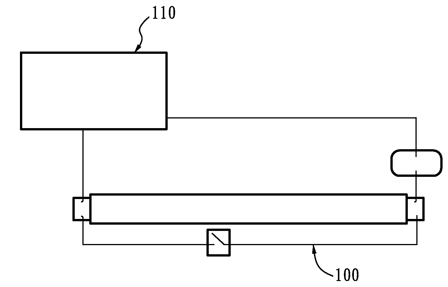
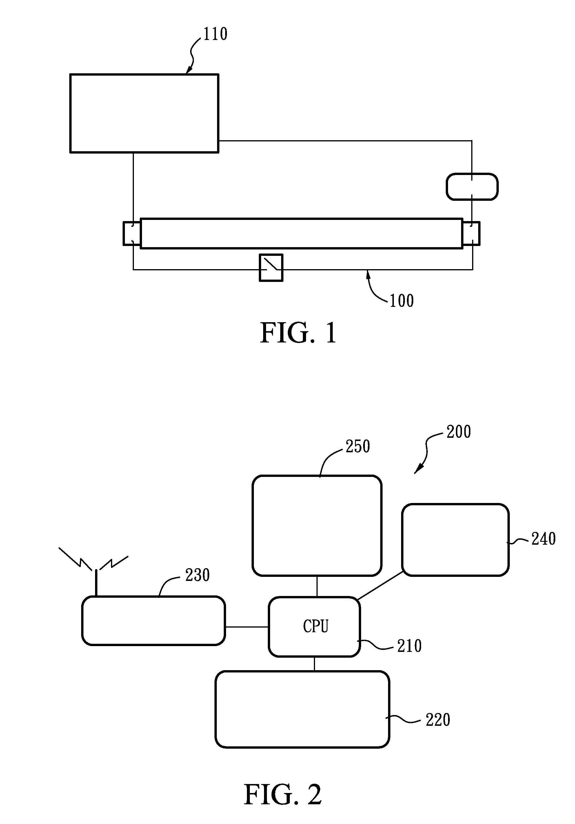
[0021]FIG. 1 is a diagram of the connecting relationship between an electronic device 100 and a transceiver 110, according to an embodiment of the present invention, wherein the electronic device 100 is a lamp in the embodiment. The electronic device 100 has an RFID tag (not shown) and a transceiver 110, and the transceiver 110 is connected with the electronic device 100. Because the electronic device 100 has a unique RFID tag associated with an RFID tag code, the transceiver 110 only receives or transmits signals with the RFID tag code. The electronic device 100 can also connect a switch control in parallel or arrange a bypass switch loop (not shown), which is compatible with existing underground conduits or open conduits, so as to manually control the electronic device 100; thus, the electronic device is more secure and maintenance is carried out conveniently as well.

[0022]FIG. 2 is a structure block diagram of a controller 200. The controller 200 comprises a central processor uni...


PUM


Abstract

A system of RFID wireless control comprises: at least one electronic device having an RFID tag and a receiver, and a controller having a reader for reading and recording the RFID tag of the at least one electronic device to form a list of electronic devices. The electronic device to be controlled is selected from the list, and the controller transmits or receives signals to or from the selected electronic device. The present invention also discloses a method of RFID wireless control for an RFID system.

Description

BACKGROUND OF THE INVENTION[0001]1. Field of the Invention[0002]The present invention relates to a system and method of wireless control. In particular, the present invention relates to a system and method of wireless control using radio frequency identification (RFID).[0003]2. Description of the Prior Art[0004]Nowadays some home appliances powered by electricity use a control loop placed in pre-installed underground conduits when a building and a mechanical “ON / OFF” switch, for example, fixed lighting and the like, are constructed. The method of control using pre-installed conduits has shortcomings: it requires locations and numbers of fixed switches. Once conduits are installed firmly, it is difficult to add extra switches, change locations, or even carry out the function of remote control with original conduits. If extra fixed lighting is to be added, it can be implemented by open conduits, which ruin the appearance of the building, or by underground conduits (or decoration), whi...

Claims


Application Information

Patent Timeline
Patent Type & Authority Applications(United States)
IPC IPC(8): G08B13/22
CPCG06K19/0723H04Q9/00H04Q2209/47G06K17/0022G06K7/0008
Inventor HSIAO, JUE-HSUANCHEN, YI-HUA
Owner HSIAO JUE HSUAN
Why Eureka
Try Eureka