Display device and method of manufacturing the same

a technology of display device and display screen, which is applied in the direction of static indicating device, non-linear optics, instruments, etc., can solve the problems of reducing the display quality of images and undesirable consequences of disposing lcd devices

Inactive Publication Date: 2009-10-15
SAMSUNG DISPLAY CO LTD
View PDF6 Cites 33 Cited by
  • Summary
  • Abstract
  • Description
  • Claims
  • Application Information

AI Technical Summary

Benefits of technology

[0010]Since an LCD device includes the top chassis coupled to the receiving container, and the mold frame disposed along an edge portion of the receiving container to support the LCD panel, there may be undesirable consequences in disposing the LCD device outdoors where the foreign matter is included. For example, the foreign matter may flow into an inner space of the receiving container through a space between the mold frame and the top chassis. Consequently, the foreign matter flowing into the receiving container may undesirably reduce the display quality of the images.
[0011]Exemplary embodiments of the present invention provide a display device capable of reducing or effectively preventing foreign matter, such as fine particles, from flowing into an inner space thereof.
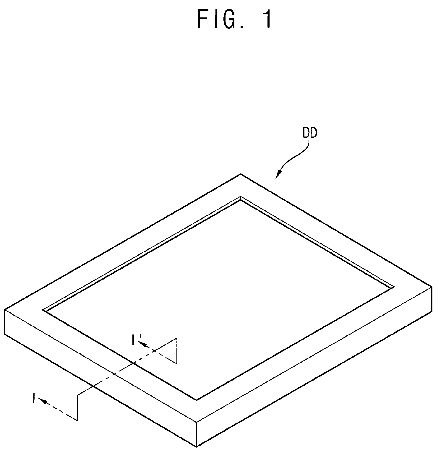
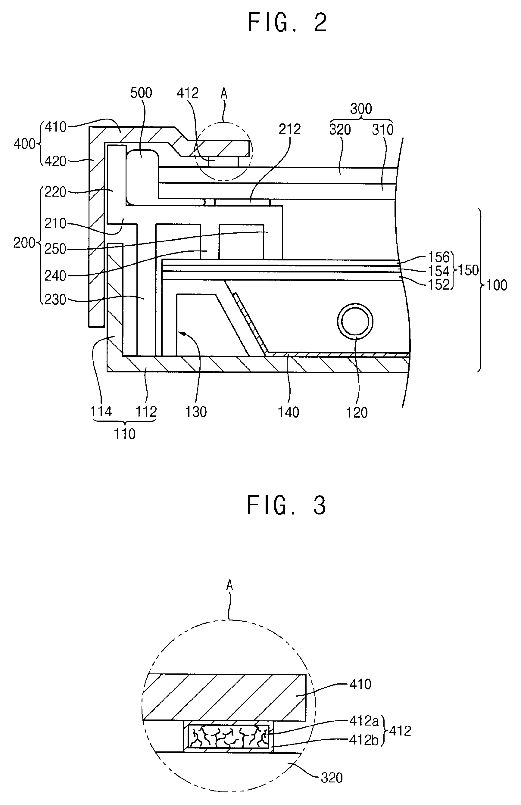
[0013]In an exemplary embodiment, a display device includes a backlight assembly, a display panel, a top chassis and a sealing member. The backlight assembly includes a light-generating unit generating light, a receiving container receiving the light-generating unit and a mold frame disposed along an edge portion of the receiving container. The display panel is disposed on the mold frame to display images by using the light. The top chassis is coupled to the receiving container to cover an edge portion of the display panel and to fix the display panel. The sealing member is disposed between the mold frame and the top chassis to surround an end portion of the display panel to fully seal a space between the end portion of the display panel and the mold frame. The sealing member has elasticity, insulating properties and adsorption capacity for foreign matter.
[0015]In an exemplary embodiment of the present invention, the sealing member may fully seal a space between the end portion of the display panel and the mold side part. The sealing member may contact the end portion of the display panel and an edge portion of a lower surface of the display panel. The sealing member may contact the end portion of the display panel and an edge portion of an upper surface of the display panel. Alternatively, the sealing member may contact the end portion of the display panel, an edge portion of a lower surface of the display panel, and an edge portion of an upper surface of the display panel.
[0017]In an exemplary embodiment of the present invention, the sealing member may include a silicon material. Alternatively, the sealing member may include a plastic material having high elasticity.
[0026]In an exemplary embodiment of the present invention, the sealing member is disposed between the mold frame and the top chassis to surround an end portion of the display panel, so as to fully seal a space between the end portion of the display panel and the mold side part. Advantageously, entering of foreign matter such as fine particles between the mold frame and the top chassis may be reduced or effectively prevented.

Problems solved by technology

Since an LCD device includes the top chassis coupled to the receiving container, and the mold frame disposed along an edge portion of the receiving container to support the LCD panel, there may be undesirable consequences in disposing the LCD device outdoors where the foreign matter is included.
Consequently, the foreign matter flowing into the receiving container may undesirably reduce the display quality of the images.

Method used


Image

  • Display device and method of manufacturing the same
  • Display device and method of manufacturing the same
  • Display device and method of manufacturing the same

Examples


Embodiment Construction

[0038]The present invention is described more fully hereinafter with reference to the accompanying drawings, in which exemplary embodiments of the present invention are shown. The present invention may, however, be embodied in many different forms and should not be construed as limited to the exemplary embodiments set forth herein. Rather, these exemplary embodiments are provided so that this disclosure will be thorough and complete, and will fully convey the scope of the present invention to those skilled in the art. In the drawings, the sizes and relative sizes of layers and regions may be exaggerated for clarity.

[0039]It will be understood that when an element or layer is referred to as being “on,”“connected to” or “coupled to” another element or layer, it can be directly on, connected or coupled to the other element or layer or intervening elements or layers may be present. In contrast, when an element is referred to as being “directly on,”“directly connected to” or “directly co...


PUM

PropertyMeasurementUnit
elasticityaaaaaaaaaa
insulating propertiesaaaaaaaaaa
adsorption capacityaaaaaaaaaa

Abstract

A display device includes a backlight assembly, a display panel, a top chassis and a sealing member. The backlight assembly includes a light-generating unit, a receiving container receiving the light-generating unit and a mold frame disposed along an edge portion of the receiving container. The display panel is disposed on the mold frame. The top chassis is coupled to the receiving container, covers an edge portion of the display panel and fixes the display panel by. The sealing member is disposed between the mold frame and the top chassis to surround an end portion of the display panel, such as to fully seal a space between the end portion of the display panel and the mold frame. The sealing member has elasticity, insulating properties and adsorption capacity for foreign matter.

Description

[0001]This application claims priority to Korean Patent Application No. 2008-34703 filed on Apr. 15, 2008, and all the benefits accruing under 35 U.S.C. § 119, the contents of which are herein incorporated by reference in their entirety.BACKGROUND OF THE INVENTION[0002]1. Field of the Invention[0003]The present invention relates to a display device and a method of manufacturing the display device. More particularly, the present invention relates to a display device displaying images by using light transmittance of liquid crystal and a method of manufacturing the display device.[0004]2. Description of the Related Art[0005]A liquid crystal display (“LCD”) device displays images using liquid crystal that has optical characteristics such as anisotropy of refractivity and electrical characteristics such as anisotropy of dielectric constant. The LCD device includes an LCD panel displaying images using optical transmittance of liquid crystal molecules and a backlight assembly disposed belo...

Claims


Application Information

Patent Timeline
Patent Type & Authority Applications(United States)
IPC IPC(8): G09G3/36G02F1/1339
CPCG02F2001/133311G02F1/133308G02F1/133311G02F1/1333G02F1/1335
Inventor JANG, JAE-WOOLEE, YOUNG-JAECHO, JIN-HOLEE, CHUL-WOOYUN, JONG-YOUNGLEE, NEUNG-BEOM
Owner SAMSUNG DISPLAY CO LTD
Why Eureka
Try Eureka