

Light emitting device and display device using same
- Summary
- Abstract
- Description
- Claims
- Application Information
AI Technical Summary
Benefits of technology
Problems solved by technology
Method used
Image

Examples
Embodiment Construction
[0030]Hereinafter, exemplary embodiments of the present invention will be described in detail with reference to the accompanying drawings.
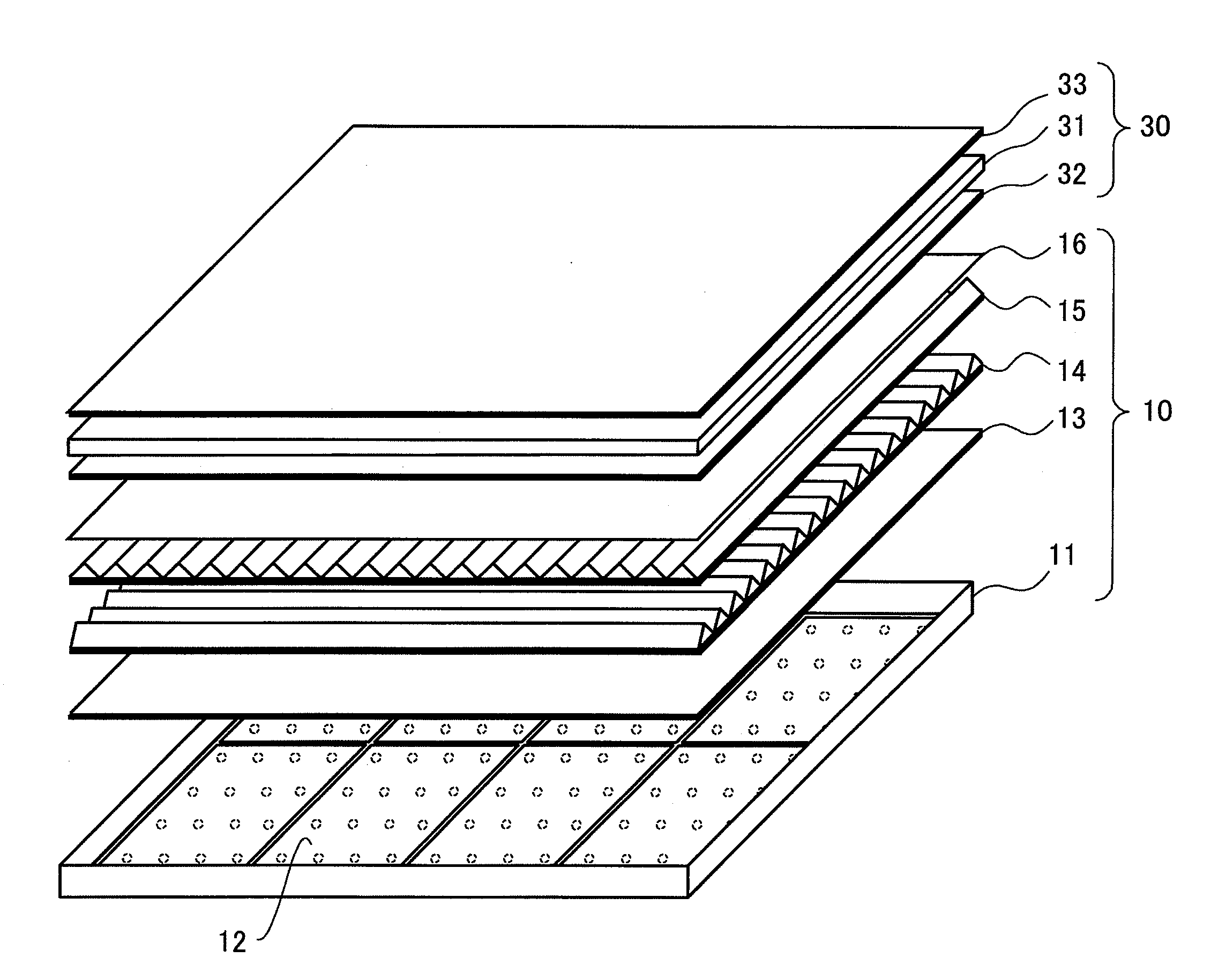
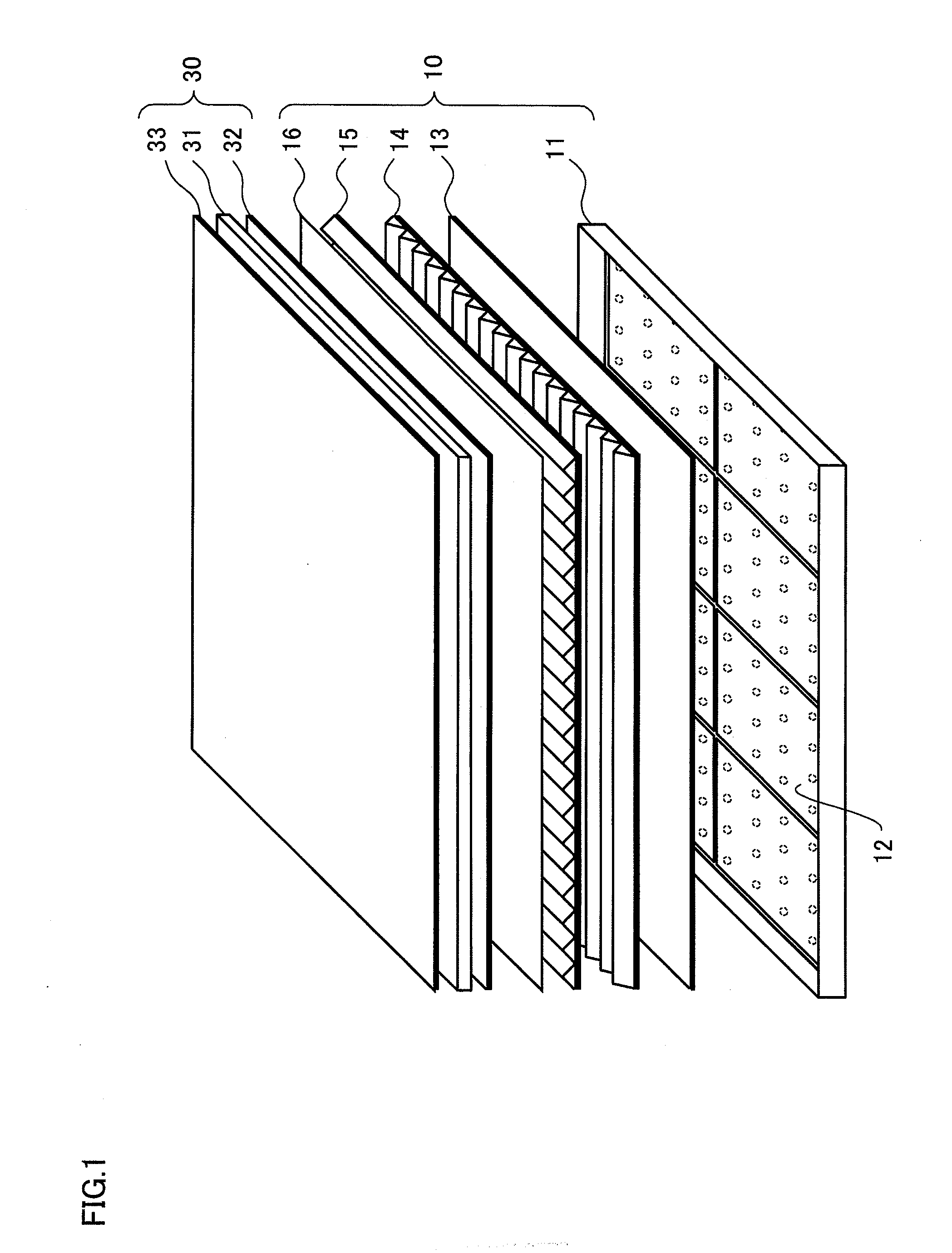
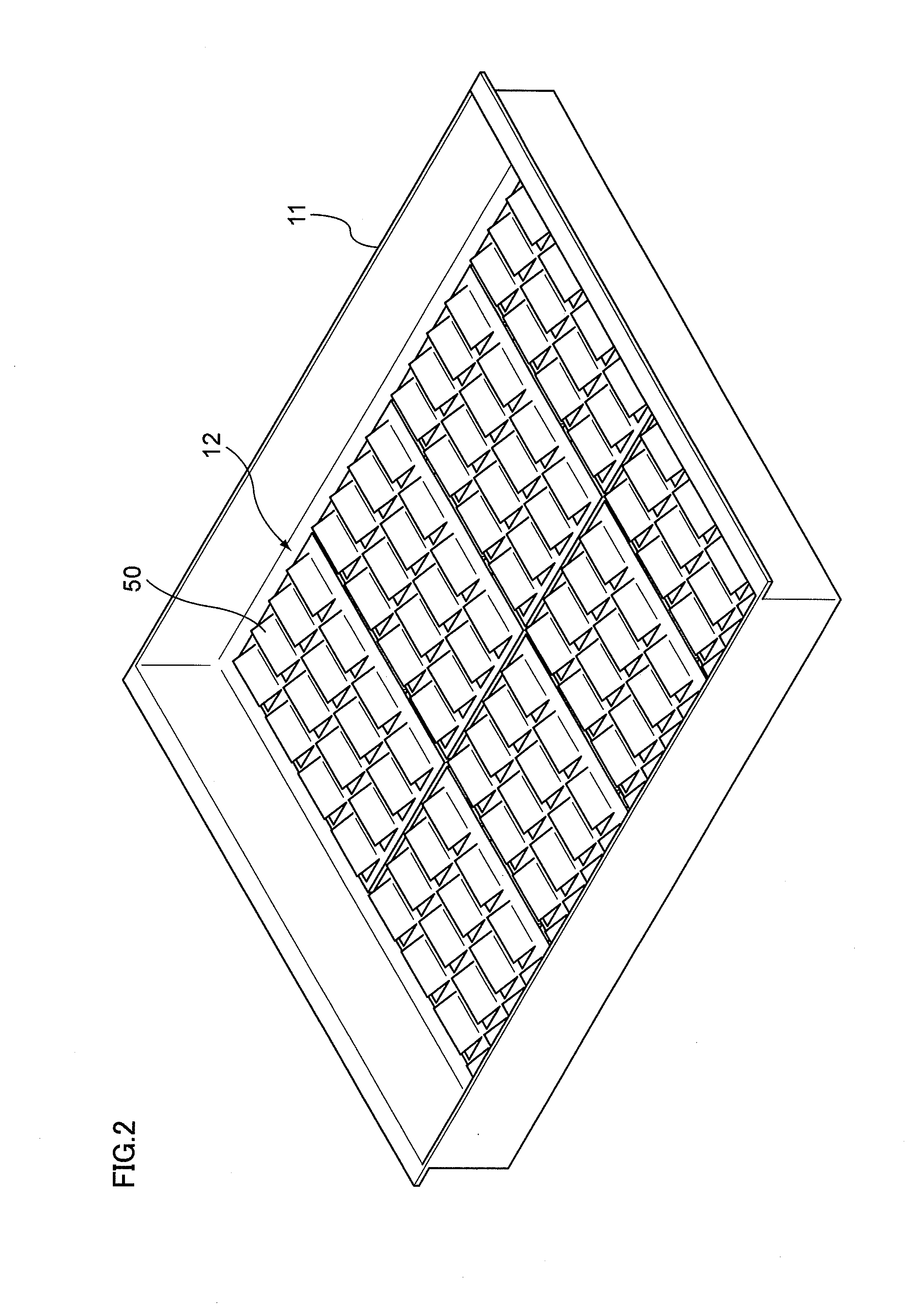
[0031]FIG. 1 is an entire configuration of a liquid crystal display device to which an exemplary embodiment is applied. The liquid crystal display device to which the present exemplary embodiment is applied, as a direct lighting type backlight device (backlight) 10, includes a backlight frame 11 that contains a light-emitting portion, and a LED substrate (mounting substrate) 12 as a substrate on which plural light-emitting diodes (LEDs) that are one type of a solid-state light-emitting element as a light-emitting source are arrayed. Moreover, the backlight device 10 includes, as a laminate of optical films, a diffusion plate 13 which is a transparent plate for scattering and diffusing light to equalize the lightness over the entire surface, and prism sheets 14 and 15 as a diffraction grating film that has a light collection effect to the front. A ...
PUM
 Abstract
Description
Claims
Application Information