Vertical axis windmill with weather vane positioning

a technology of windmills and vertical axes, which is applied in the direction of machines/engines, renewable energy generation, and final product manufacturing, etc., can solve the problems of limiting the amount of energy that can be collected, and achieve the effect of maximizing the torque produced

Inactive Publication Date: 2009-10-15
RICE KARL MARVIN
View PDF11 Cites 10 Cited by
  • Summary
  • Abstract
  • Description
  • Claims
  • Application Information

AI Technical Summary

Benefits of technology

[0007]Large flat blades are put on the ends of long lever arms to maximize the torque produced at a central vertical shaft. Pivoting each blade on its own axis allows it to be positioned to best advantage as it rotates around the central vertical shaft. The positioning is accomplished by gearing the blade to a central control gear. By simply attaching a weather vane to the central control gear, the direction of the entire windmill is controlled.
[0008]In each revolution, the outer edge of a blade becomes the inner edge of the blade and the inner edge becomes the outer edge, this eliminates the over-run problem almost completely.
[0010]The gears can be very simple, they just need to preserve a 1:2 gear ratio.
[0011]The entire windmill can easily be built on a large enough scale to capture significant energy, for a family living in a windy area.

Problems solved by technology

As you try to add surface area this will lead to an “over-run” problem where the outer edge of the blade is actually trying to push the wind faster than it is going.
Horizontal axis windmills also require a tower structure to hold them up and become very vulnerable in high winds.
The vertical axis designs I have looked at, either still have an over-run problem or have sacrificed surface area to remain omni-directional greatly limiting the energy that can be collected.

Method used


Image

  • Vertical axis windmill with weather vane positioning
  • Vertical axis windmill with weather vane positioning
  • Vertical axis windmill with weather vane positioning

Examples


Embodiment Construction

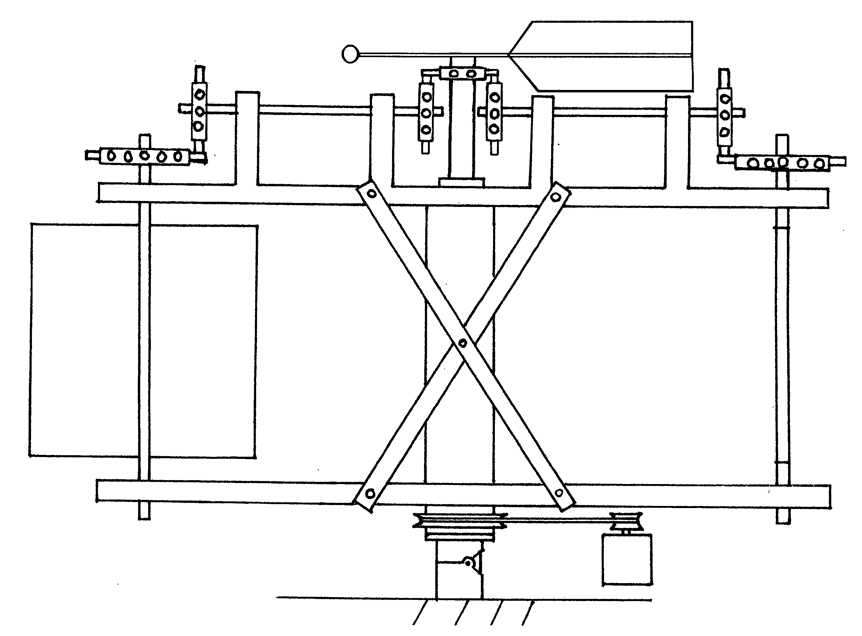
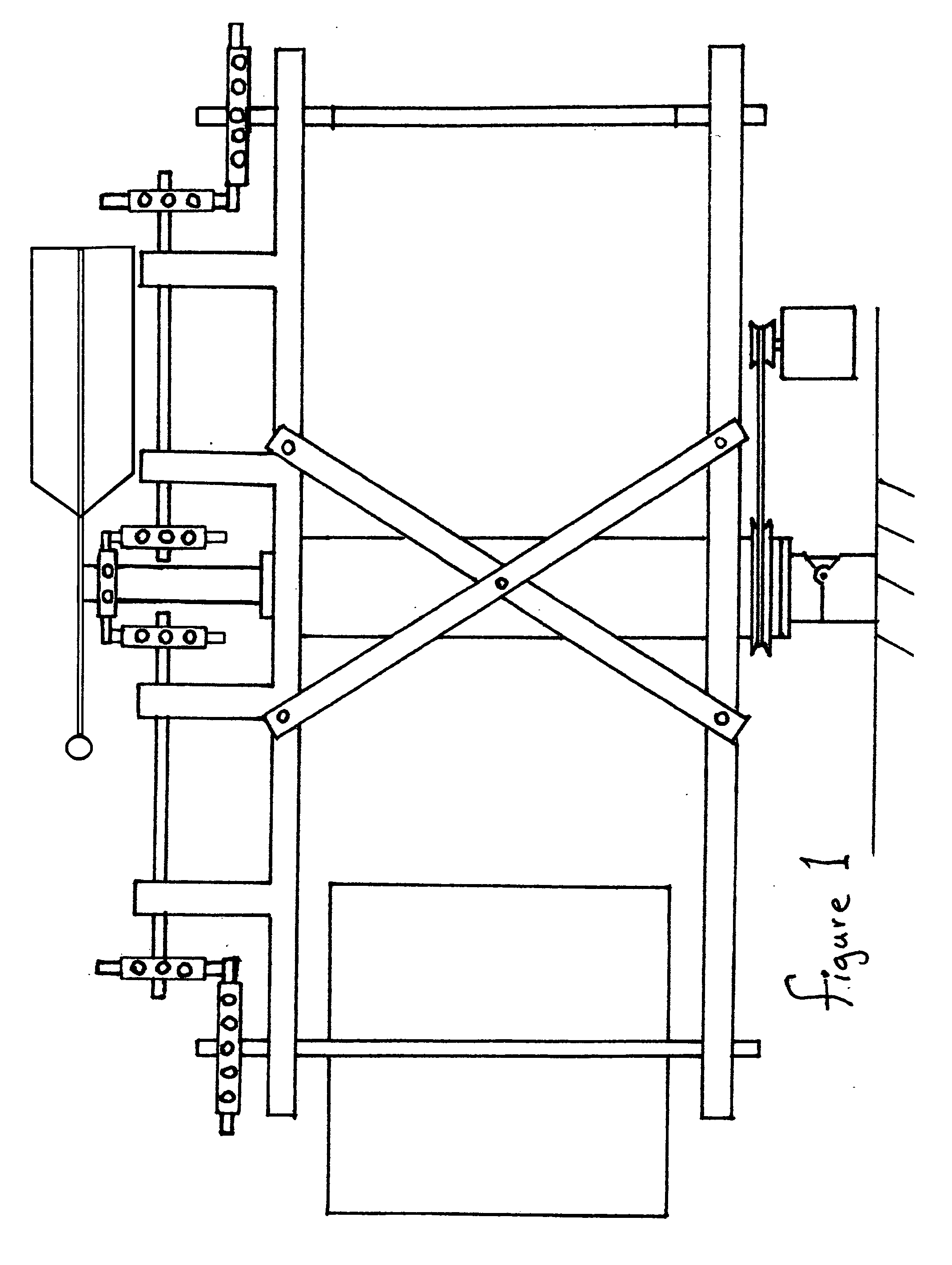
Assembling the Machine:

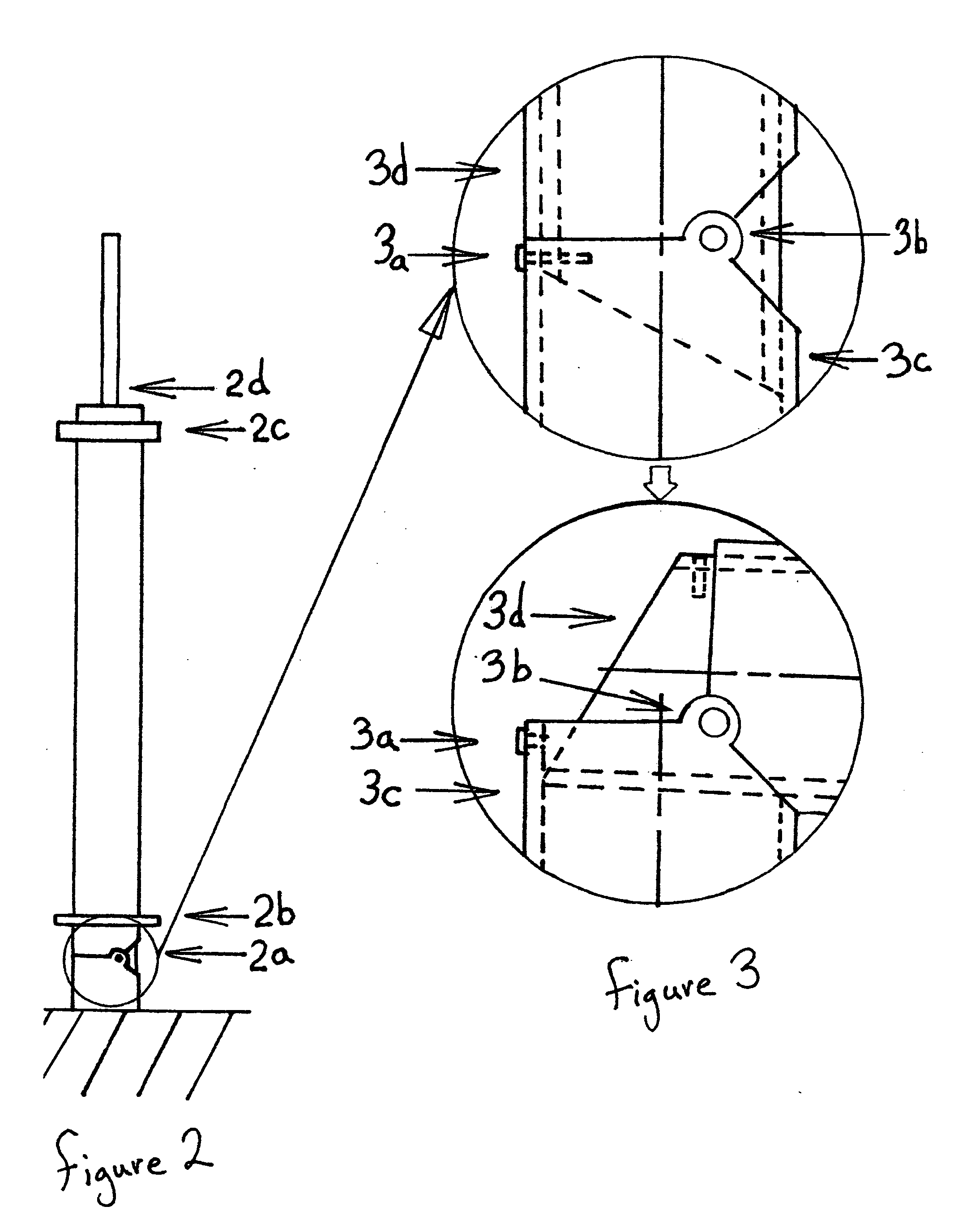
[0050]The anchor shaft (3c) is anchored in the ground, checked to be vertical and cemented in place.

[0051]The windmill blade proper (5b) is attached to the blade shaft (5a). The gear shaft supports (4g) are attached to the upper arm (4f) of the frame and the connecting gear shafts (7c) are put into their supports. Attach a connecting gear (7a) and (7b) to each end of the connecting gear shafts.

[0052]The lower arm (4c) is put on the main tube (4a). The windmill blade shafts (5a) are put through the holes in the lower arm (4e) then they are inserted into the holes in the upper arm (4e). The upper arm (4f) is attached to the main tube (4a). The support braces (4d) are added for rigidity. The power pulley (4b) is attached to the bottom of the main tube (4a) and the frame is complete.

[0053]Now attach the blade gears (5c) on top of the blade shafts (5a). Insert the mast shaft (3d) into the frame (FIG. 4). Attach the central gear (6a) to the weather vane (6b).

[0054]P...


PUM


Abstract

Large flat blades are put on the ends of long lever arms to maximize the torque produced at a central vertical shaft. Pivoting each blade on its own axis allows it to be positioned to best advantage as it rotates around the central vertical shaft. The positioning is accomplished by gearing the blade to a central control gear. By simply attaching a weather vane to the central control gear, the direction of the entire windmill is controlled.

Description

[0001]This application claims priority of Provisional Patent Application No. 60 / 925,824 filed on Apr. 23, 2007CROSS-REFERENCE TO RELATED APPLICATIONS[0002]Not ApplicableSTATEMENT REGARDING FEDERALLY SPONSORED RESEARCH OR DEVELOPMENT[0003]Not ApplicableREFERENCE TO SEQUENCE LISTING, A TABLE, OR A COMPUTER PROGRAM LISTING COMPACT DISC APPENDIX[0004]Not ApplicableBACKGROUND OF THE INVENTION[0005]What is the best way to harness the energy of the wind? To gather much energy you need sails or blades with large surface area. With most horizontal axis type windmills the blades are laid out as some part of a circle. As it goes around, the inner edge has much less distance to travel per revolution than the outer edge. As you try to add surface area this will lead to an “over-run” problem where the outer edge of the blade is actually trying to push the wind faster than it is going. So instead of collecting energy the outer edge is dissipating part of the energy that the middle and inner side o...

Claims


Application Information

Patent Timeline
Patent Type & Authority Applications(United States)
IPC IPC(8): F03D7/06F03D3/00
CPCF03D1/001F03D3/068F05B2230/60F05B2240/91521Y02E10/74F05B2260/4021F05B2260/403Y02E10/728F05B2260/402F03D13/10Y02P70/50
Inventor RICE, KARL MARVIN
Owner RICE KARL MARVIN
Why Eureka
Try Eureka