Method for optimizing fuel injection timing in a compression ignition engine

a technology of compression ignition and timing optimization, which is applied in the direction of electrical control, process and machine control, instruments, etc., can solve the problems of no means provided for adjusting calibrations to re-, no longer optimal fuel injection calibrations, and increased torque, etc., to maximize the fuel economy of each cylinder, increase or decrease the amount of torque, the effect of maximizing the torqu

Active Publication Date: 2009-09-22
DELPHI TECH IP LTD
View PDF10 Cites 1 Cited by
  • Summary
  • Abstract
  • Description
  • Claims
  • Application Information

AI Technical Summary

Benefits of technology

[0007]Briefly described, a CI engine is provided with means, such as a pressure sensor, disposed in one or more cylinders (and preferably all cylinders) for measuring instantaneously the Indicated Mean Effective Pressure (IMEP) in the cylinder. The operating principle of the invention is that the pressure level in the cylinder during the power stroke of a piston is a direct indicator of engine torque being generated, and that the timing of fuel injection can increase or decrease the amount of torque. Thus, there is a maximum torque value which can be obtained by optimizing the timing of fuel injection. For the engine operating conditions pertaining at any time of engine operation, an algorithm in the ECM varies the timing of fuel injection in a narrow range until a IMEP maximum is achieved, which timing is then retained and employed until the engine operating conditions change. Thus, the invention maximizes the fuel economy of each cylinder by maximizing the torque obtained from each injection of fuel into the cylinders.

Problems solved by technology

With prolonged use, an engine may undergo changes in the engine itself, or in fuel properties, such that the programmed fuel injection calibrations are no longer optimum.
In prior art engines, no means is provided for adjusting the calibrations to re-optimize fuel injection timing for each cylinder through the operating life of the engine.

Method used


Image

  • Method for optimizing fuel injection timing in a compression ignition engine
  • Method for optimizing fuel injection timing in a compression ignition engine
  • Method for optimizing fuel injection timing in a compression ignition engine

Examples


Embodiment Construction

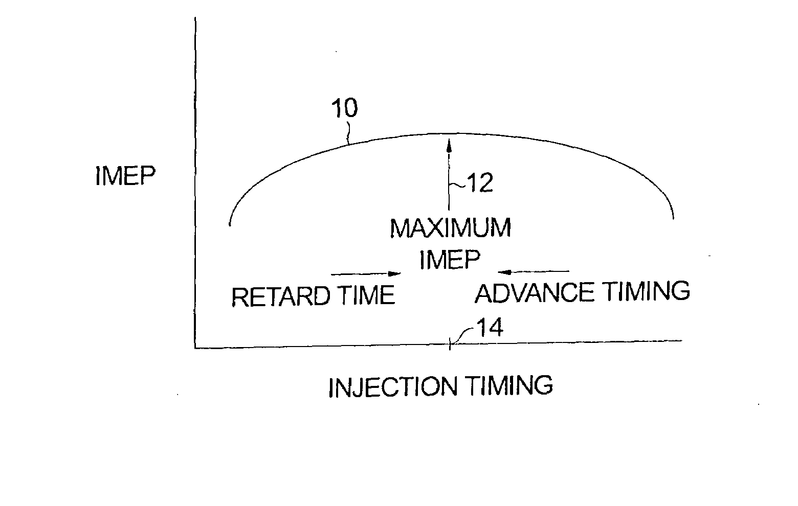
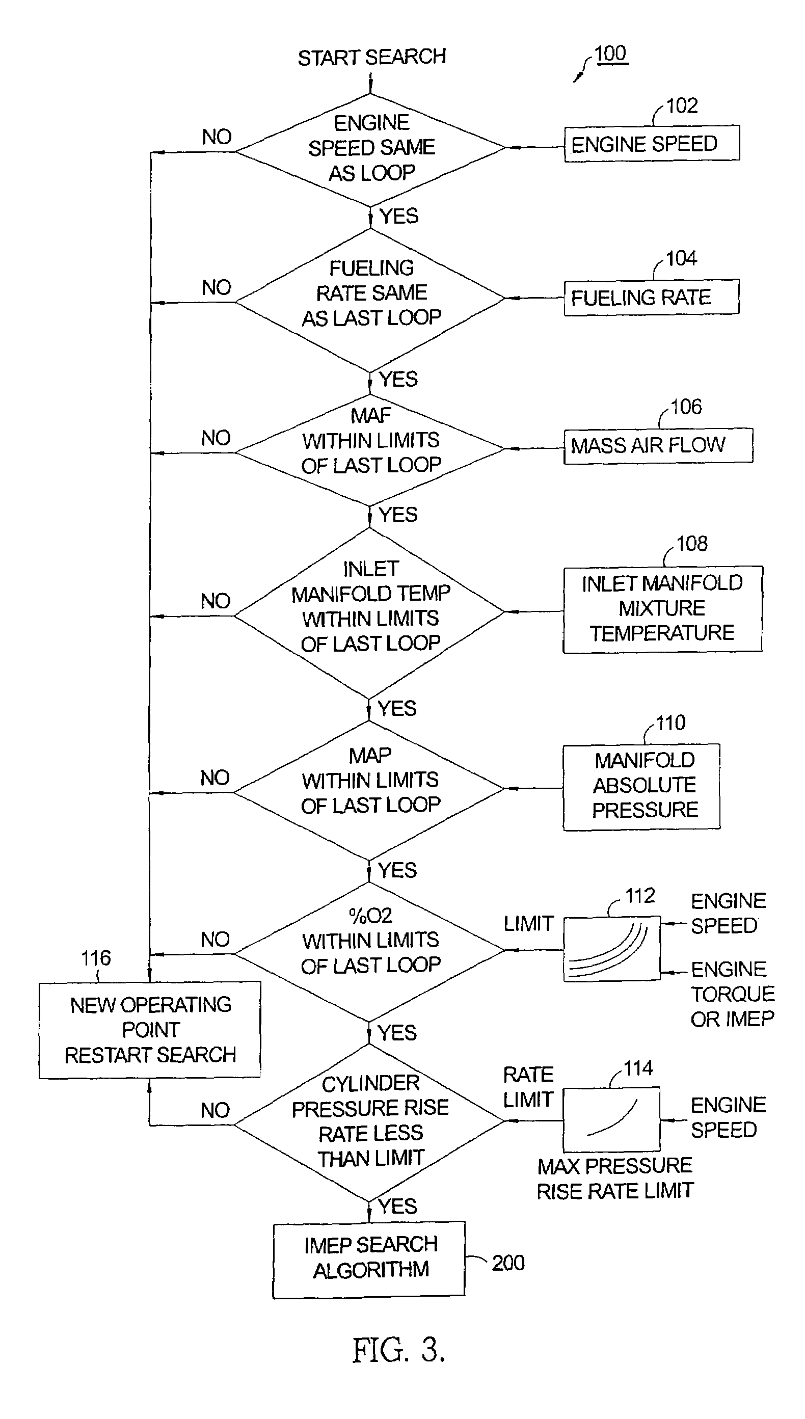
[0014]In a method in accordance with the invention for optimizing the injection timing of fuel injectors in each cylinder of a CI engine, the engine operating parameters are checked to see if the engine is in a stable operating condition; if so, then a search routine can begin for the injection timing that produces the maximum IMEP reading for a given fueling rate.

[0015]There is a unique injection timing angle that produces the maximum IMEP, which maximum and thus angle may be found by a search algorithm. (The timing “angle” is the rotational angle of the crankshaft before top dead center of the piston in the cylinder at which fuel injection is initiated.) When the injection angle is found that produces the maximum IMEP, that angle is stored in memory. This value can be used for injection timing when the algorithm is not in search routine mode because the engine is not in steady state condition. Also, the search algorithm will help to adjust the injection timing for changes in fuel ...


PUM


Abstract

A method for determining the optimum fuel injection timing angle in a CI engine provided with means disposed in one or more cylinders for measuring Indicated Mean Effective Pressure. The pressure level during the power stroke of a piston is a direct correlate of engine torque being generated, and the timing of fuel injection can increase or decrease the amount of torque. Thus, maximum torque can be obtained by optimizing the timing of fuel injection. An algorithm in the ECM varies the timing of fuel injection in a narrow range until a IMEP maximum is achieved, which timing is then retained and employed until the engine operating conditions change. Thus, the invention can optimize fuel economy by optimizing the torque obtained from each injection of fuel into the cylinders.

Description

TECHNICAL FIELD[0001]The present invention relates to compression-ignited (CI) internal combustion engines; more particularly, to methods for timing the injection of fuel into the cylinders of CI engines; and most particularly, to a method for optimizing fuel injection timing to provide maximum torque for a given amount of injected fuel.BACKGROUND OF THE INVENTION[0002]CI engines require injection of fuel into the cylinders during the compression stroke of each piston. The fuel is ignited when sufficient compression and temperature are achieved. Hence, the timing of fuel injection or injections into the cylinders is obviously an important parameter in engine performance and fuel efficiency.[0003]In the prior art, fuel injection calibrations typically are performed on a dynamometer at the completion of engine assembly and are fixed in the memory of an associated Engine Control Module (ECM). The timing calibrations take into account at least engine speed, temperature, and throttle pos...

Claims


Application Information

Patent Timeline
Patent Type & Authority Patents(United States)
IPC IPC(8): G06F17/00
CPCF02D35/023F02D41/401F02D41/3818F02D41/1497Y02T10/44F02D2250/18Y02T10/40
Inventor FATTIC, GERALD T.
Owner DELPHI TECH IP LTD
Why Eureka
Try Eureka