Blower Impeller with Partial Tip Blockage

Active Publication Date: 2009-10-15
MINEBEAMITSUMI INC
View PDF6 Cites 3 Cited by
  • Summary
  • Abstract
  • Description
  • Claims
  • Application Information

AI Technical Summary

Benefits of technology

[0004]One of the objects of the invention is to enhance the pressure production capability

Problems solved by technology

This flow distribution profile creates an non

Method used


Image

  • Blower Impeller with Partial Tip Blockage
  • Blower Impeller with Partial Tip Blockage
  • Blower Impeller with Partial Tip Blockage

Examples


Embodiment Construction

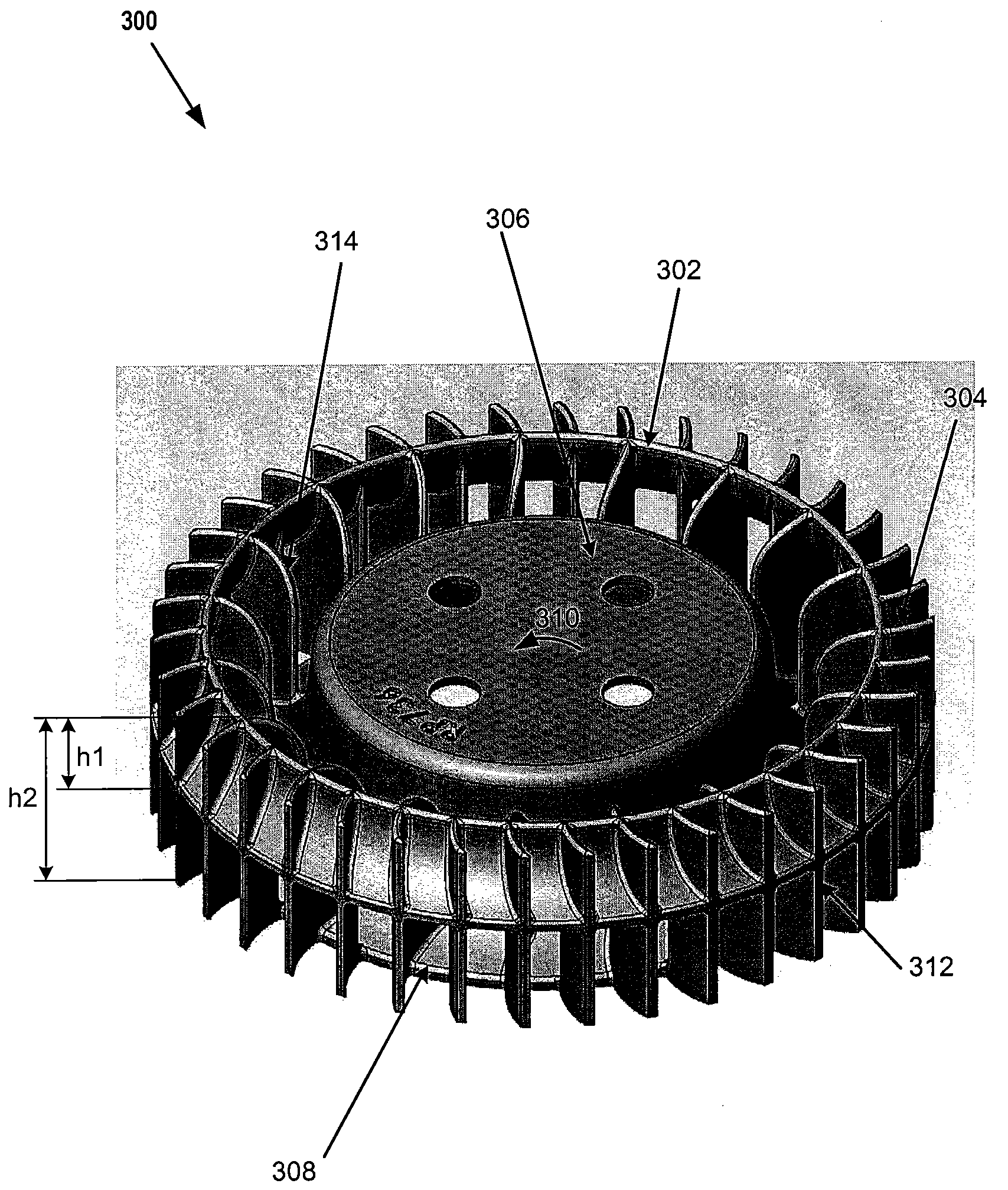
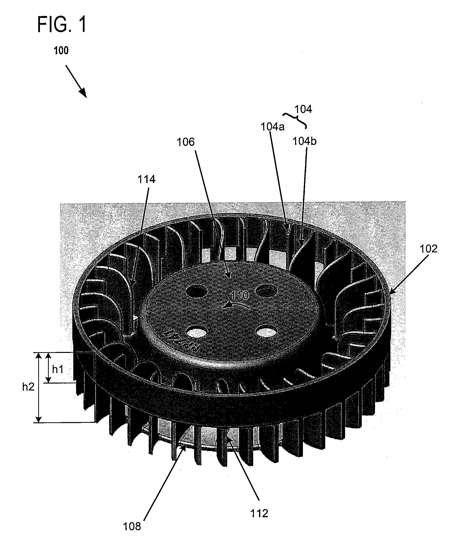
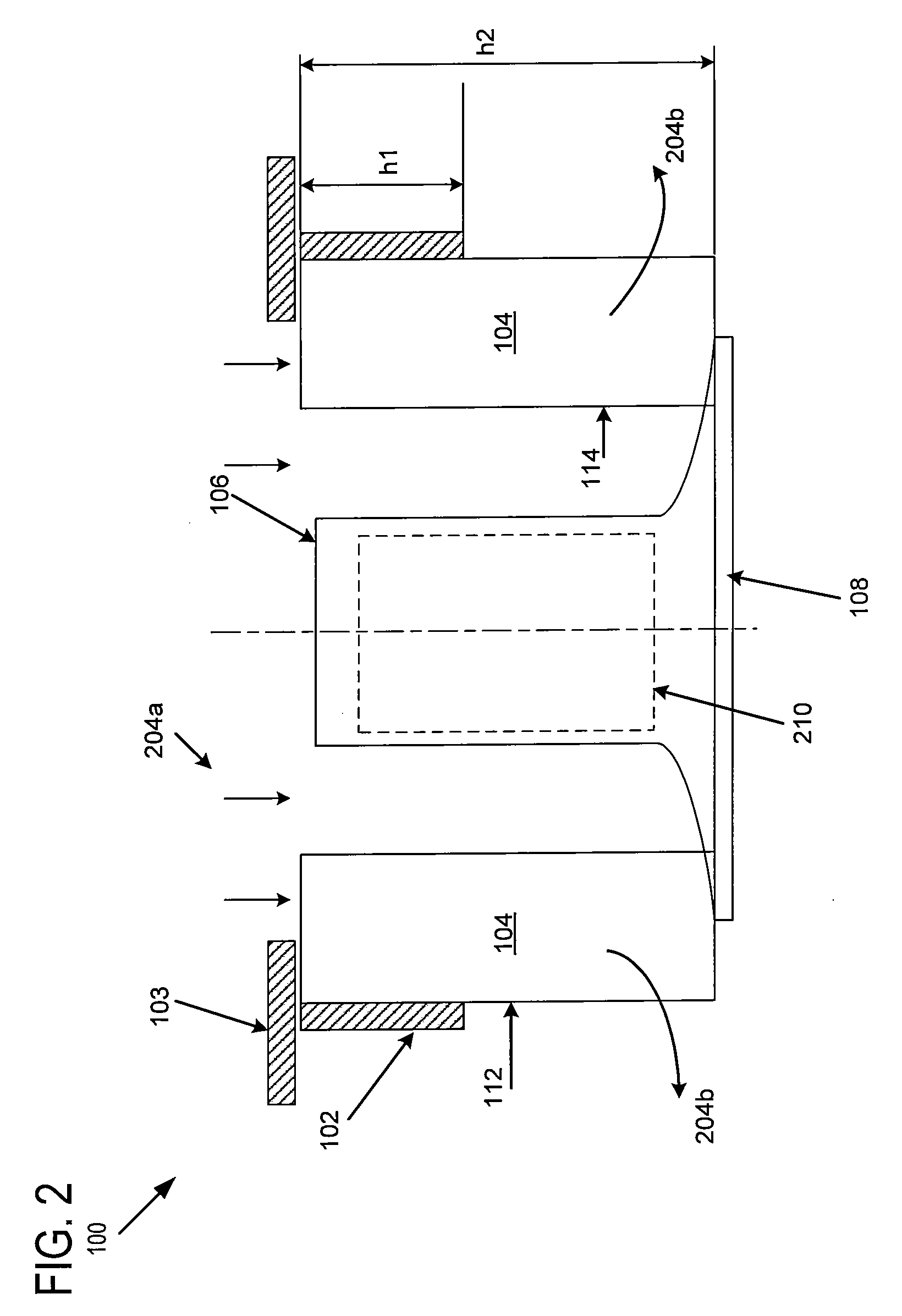
[0014]FIG. 1 illustrates an example impeller according to embodiments of the invention. FIG. 2 illustrates a cross-section view of the impeller in FIG. 1.

[0015]Referring to FIGS. 1 and 2, impeller 100 includes drive motor 210 (indicated in FIG. 2 with phantom lines) and a hub 106 into which drive motor 210 is securely fitted. A plurality of radial blades 104 are attached and disposed about hub 106. Radial blades 104 may be of varying chord length, such as splitter blades 104a and full blades 104b shown in FIG. 1. These varying-length radial blades 104, together with the tip ring 102 (which will be discussed below), reduce the tonal noise associated with the blade passing frequency.

[0016]When impeller 100 rotates in a direction indicated by arc 110, radial blades 104 capture the axially-directed air inflow 204a (as shown in FIG. 2) that enters an opening on the inlet side of the impeller via hub 106, and redirect the air inflow in a radial direction 204b (as shown in FIG. 2) toward t...


PUM


Abstract

According to embodiments of the invention, an impeller includes a hub, and a plurality of radial blades for drawing the air inflow axially through the hub and delivering the drawn air radially towards the outside. A ring is attached to one or more tips of the plurality of radial blades to block a portion of the tip toward the inlet side of the impeller. The preferred blockage factor, which is the ratio of a height of the ring to a height of the tip, is approximately in a range between 30% and 40%. By blocking a portion of the tip toward the inlet side of the impeller, the low-momentum flow zone toward the inlet side of impeller is blocked, while the high-momentum flow zone toward the back side of impeller is enhanced. As such, the performance of the impeller is enhanced.

Description

BACKGROUND OF THE INVENTION[0001]This invention relates generally to blower impellers and in particular to blower impellers with improved pressure production capability.[0002]It is well known that a blower impeller has a central hub arranged to be mounted on a motor shaft. A set of radial blades are arranged on the hub and configured to draw air axially into the interior of the hub and to deliver it radially towards the outside.[0003]There are generally two flow zones within such an impeller: a low-momentum zone toward the inlet side of the impeller and a high-momentum zone toward the back side of the impeller. This flow distribution profile creates an non-uniform air flow, which degrades performance.BRIEF SUMMARY OF THE INVENTION[0004]One of the objects of the invention is to enhance the pressure production capability of the impeller and to reduce the tonal noise associated with the blade passing frequency.[0005]According to embodiments of the invention, an impeller includes a hub,...

Claims


Application Information

Patent Timeline
IPC IPC(8): F01D5/22
CPCF04D29/188
Inventor JARRAH, YOUSEFSITU, HANSONNGUYEN, THANG
Owner MINEBEAMITSUMI INC
Why Eureka
Try Eureka