Plate-type evaporator to suppress noise and maintain thermal performance

a plate-type evaporator and noise suppression technology, which is applied in the field of evaporators, can solve the problems of tonal noise, tonal noise, and flow of cooling fluid in this type of evaporator, and achieve the effects of reducing tonal noise, suppressing or reducing flow-induced whistles, and less intensity

Active Publication Date: 2007-03-01
MAHLE INT GMBH
View PDF13 Cites 43 Cited by
  • Summary
  • Abstract
  • Description
  • Claims
  • Application Information

AI Technical Summary

Benefits of technology

[0009] The divider rib combined with smaller hemispherical dimples has proven effective in reducing tonal noise under certain conditions.
[0010] As the flow velocity increases, and when the vortex shedding frequency happens to be near the natural frequency of the gas column perpendicular to the flow direction, a strong acoustic oscillation of the gas column is excited, and it is this resonant oscillation that is perceived as a tonal noise or whistle. When acoustic resonance is excited, all the vortices are “locked” in at a certain frequency, so to say. Once this vortex locking has occurred, any increase in velocity does not affect the frequency of the pure tone, but does increase the amplitude of the excitation.
[0011] The resonant frequency is inversely proportional to the channel width in some evaporators. The shape, size, and distribution of the bumps will affect the character of the whistle by influencing the energy associated with vortex shedding. Hence, in order to suppress or mitigate the flow-induced whistle, the subject invention provides smaller dimples that are hemispherical and packed at an optimum density in a flow channel of limited width. An evaporator with these features eliminates the flow-induced whistle and also provides comparable thermal performance. Typically, the two changes of converting oblong bumps into smaller round bumps and providing a central rail to limit channel width by themselves would have resulted in a thermal performance loss. The reason for this is that although smaller round bumps may shed vortices of lesser intensity (and therefore mitigates or eliminates the whistle), they do not spread the liquid refrigerant as much as the oblong bumps do. This would cause a lower heat transfer effectiveness and lower performance. The middle rail to limit the channel width inhibits the transverse mixing of the refrigerant, which would adversely affect thermal performance. To overcome these potential losses, the round bumps are more densely packed than the oblong bumps.

Problems solved by technology

Unfortunately the flow of cooling fluid in this type of evaporator can produce a noise, particularly a “whistling”, i.e., a tonal noise emanating from a plate-type evaporator used in certain automotive climate control systems under transient conditions.
It is believed that this tonal noise occurs when gaseous refrigerant at sufficiently high velocities flows over the first dimples.
It is further believed that the tonal noise is caused by periodic flow instability (manifested as vortices) in the wake of the first dimples.

Method used


Image

  • Plate-type evaporator to suppress noise and maintain thermal performance
  • Plate-type evaporator to suppress noise and maintain thermal performance
  • Plate-type evaporator to suppress noise and maintain thermal performance

Examples


Embodiment Construction

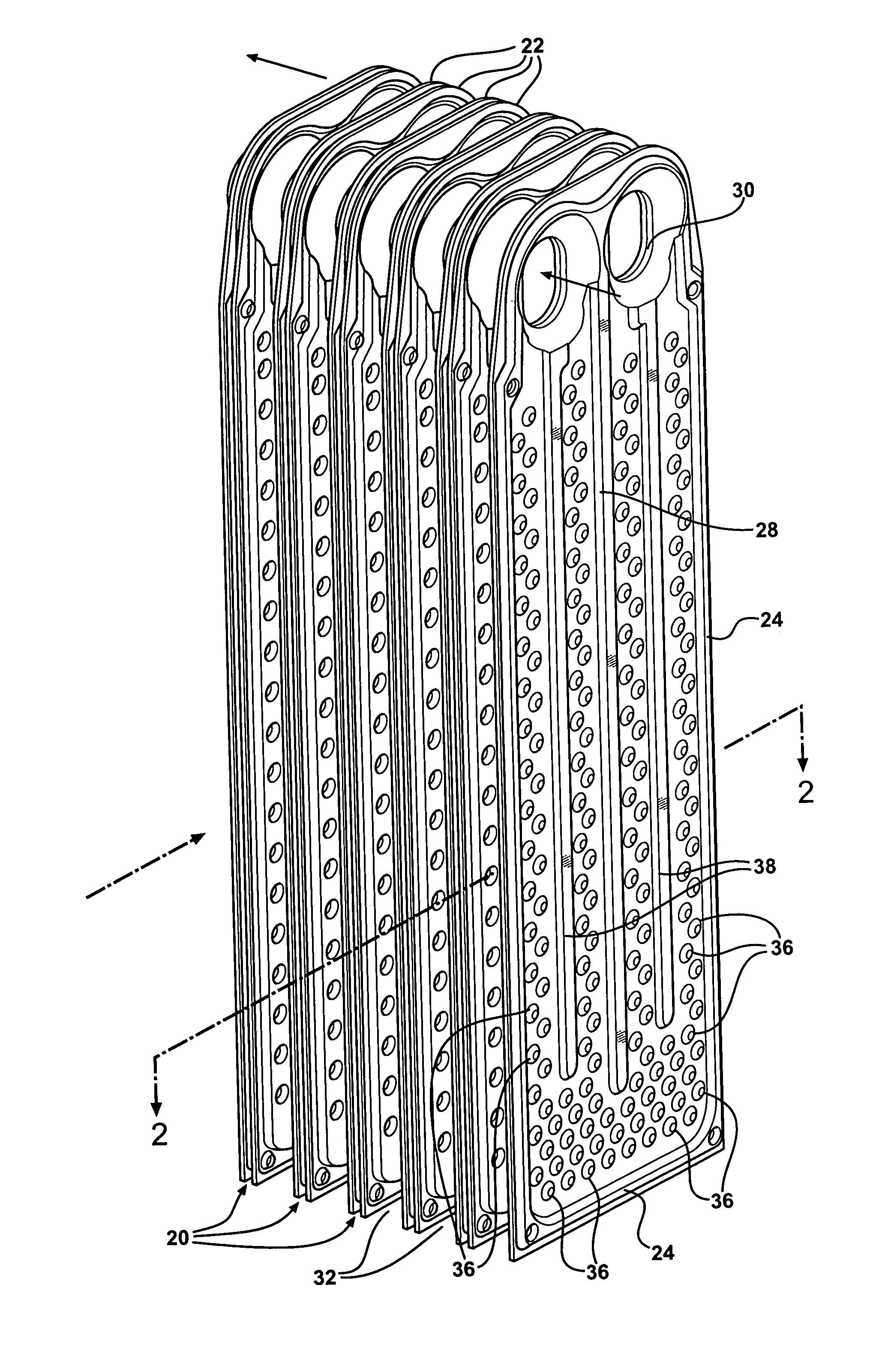
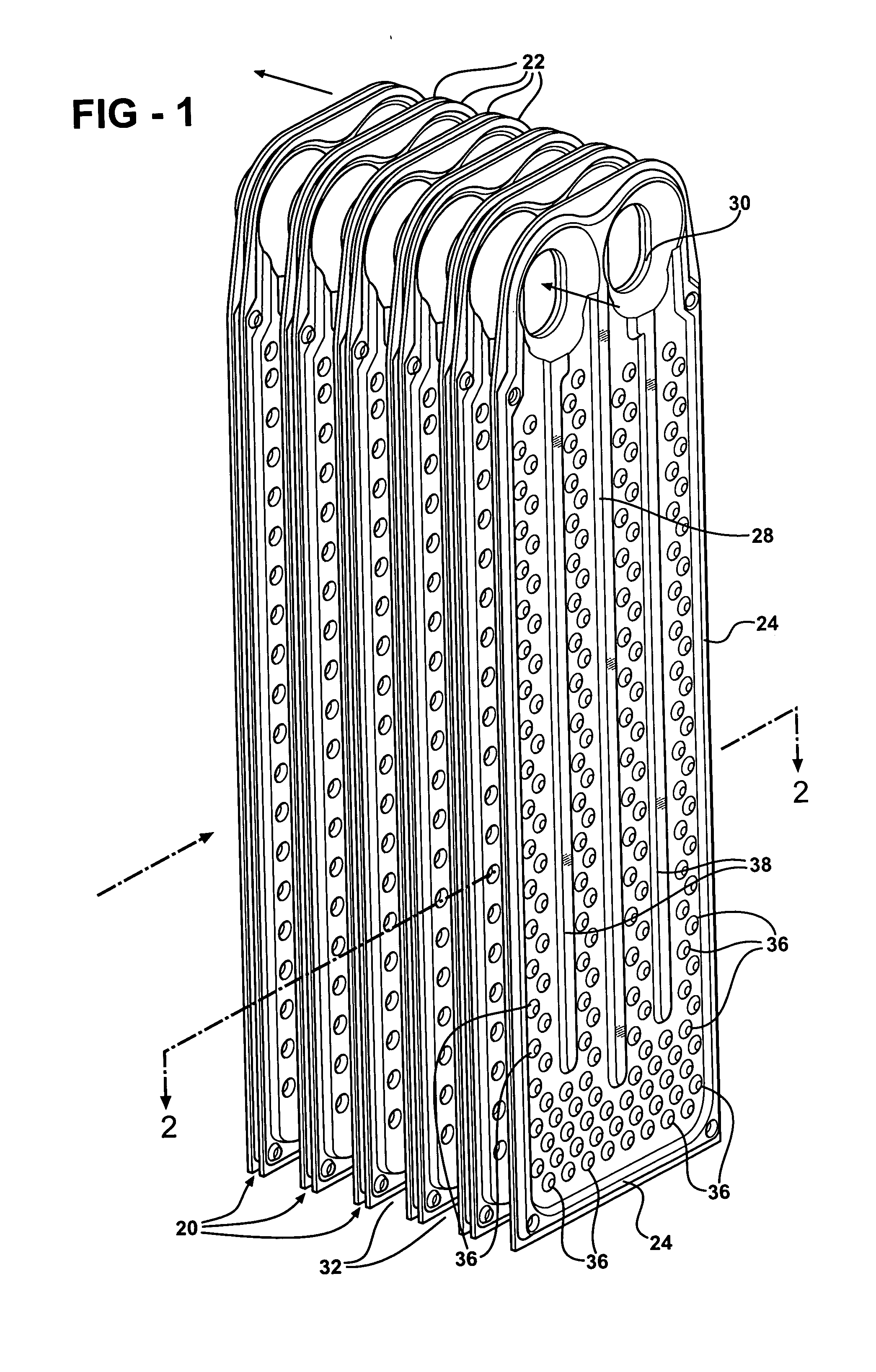
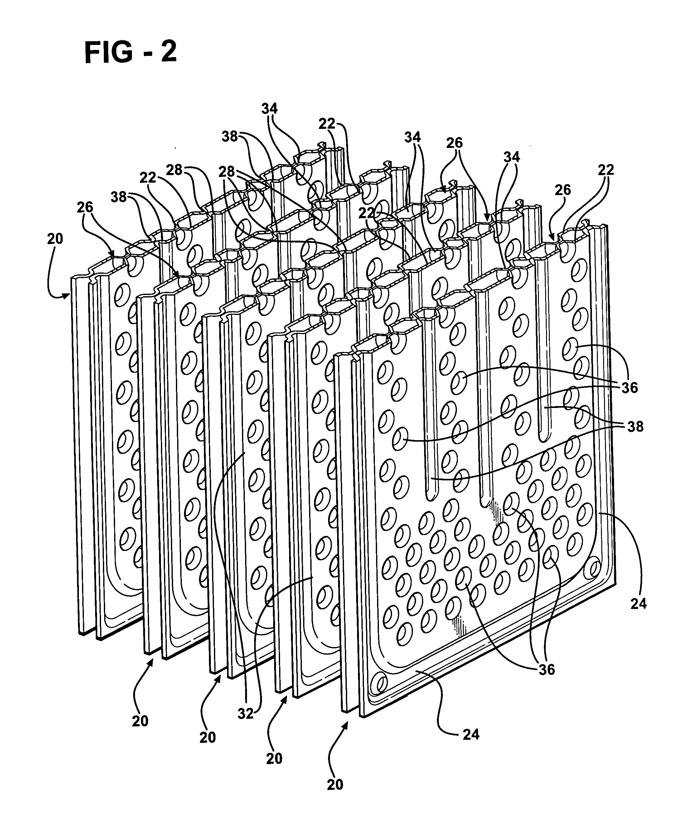
[0019] A heat exchanger assembly is variously shown in the Figures and includes as a basic component at least one pair 20 of plates 22. The plates 22 can be identical and disposed in mirror relationship to one another. The plates 22 have mating edges 24 and a concave region delimited by the edges 24 to define a fluid passage 26 between said pair 20 of plates 22. The assembly includes a plurality of pairs 20 of the plates 22 disposed in series for fluid flow from a pass through one pair 20 of plates 22 to a pass through the next pair 20 of plates 22, as illustrated by the arrows in FIG. 3. Each pair 20 of plates 22 includes a central rib 28 to define a U-shaped passage 26 having a fluid entering leg and a fluid exiting leg interconnected by an open bottom interconnecting the legs below the lower end of the engaging central ribs 28. The plates 22 have tubular projections 30 defining an inlet for entering fluid to the passage 26 and an outlet for exiting fluid from the passage 26 to th...


PUM


Abstract

A heat exchanger assembly including a plurality of pairs of plates disposed in series for fluid flow from a pass through one pair of plates to a pass through the next pair of plates. Each pair of plates includes a central rib to define a U-shaped passage having a fluid entering leg and a fluid exiting leg interconnected by an open bottom interconnecting the legs below the lower end of the engaging central ribs. A plurality of dimples project into the passage to interact with fluid flow through the passage and each of the dimples has a hemispherical shape and a divider rib is disposed in the passage to co-act with the hemispherical dimples to reduce whistling noise.

Description

BACKGROUND OF THE INVENTION [0001] 1. Field of the Invention [0002] The present invention relates to a heat exchanger assembly, and more particularly, to an evaporator for a heating and / or air conditioning system (HVAC) for automotive vehicles. [0003] 2. Description of the Prior Art [0004] An evaporator of the type to which the subject invention pertains exchanges heat between a cooling fluid and air. A stack of virtually identical plates are positioned symmetrically in pairs having mating edges and a concave region delimited by the edges to define a fluid passage. The plates have tubular projections defining an inlet for entering fluid to the passage and an outlet for exiting fluid from the passage to thereby establish a direction of fluid flow. Each inlet is connected to the outlet of the preceding pair of plates and each outlet is connected to the inlet of the next pair of plates. Actually, each pair of plates includes a central rib to define a U-shaped passage having a fluid ent...

Claims


Application Information

Patent Timeline
Patent Type & Authority Applications(United States)
IPC IPC(8): F28D1/02
CPCF28D1/0341F28F3/044F28F3/046
Inventor MEHENDALE, SUNIL S.VREELAND, GARY SCOTTLIPA, SCOTT B.
Owner MAHLE INT GMBH
Why Eureka
Try Eureka