Operation of a coordinate measuring machine

a technology of coordinate measuring machine and measuring machine, which is applied in the direction of instruments, measurement devices, computing, etc., can solve problems such as affecting oscillation susceptibility, and achieve the effect of reducing the speed of the machine part and improving the precision of the operation of the machin

Active Publication Date: 2015-12-08
CARL ZEISS IND MESSTECHN GMBH
View PDF29 Cites 0 Cited by
  • Summary
  • Abstract
  • Description
  • Claims
  • Application Information

AI Technical Summary

Benefits of technology

[0018]The method is particularly advantageous when the movement is a movement whereby the machine part is moved closer to a workpiece in order to contact the workpiece, wherein the movement has a movement phase whereby the speed of the machine part decreases. An example of such a movement has been explained above. If the acceleration (in particular with regard to its amount) is limited during the braking phase and / or if the jerk (in particular with regard to its amount) is limited, oscillations can be effectively avoided during such a movement. Such a movement phase is particularly important for the precision of the operation of the machine as oscillations generated during the braking phase can still last until contact with the workpiece is produced. Also the correct position at which the workpiece is to be contacted can possibly not be reached or can only be reached in a non-precise manner when the oscillations are still continuing.

Problems solved by technology

However, the state of the suspension of the arm can also influence the oscillation susceptibility.

Method used


Image

  • Operation of a coordinate measuring machine
  • Operation of a coordinate measuring machine
  • Operation of a coordinate measuring machine

Examples


Embodiment Construction

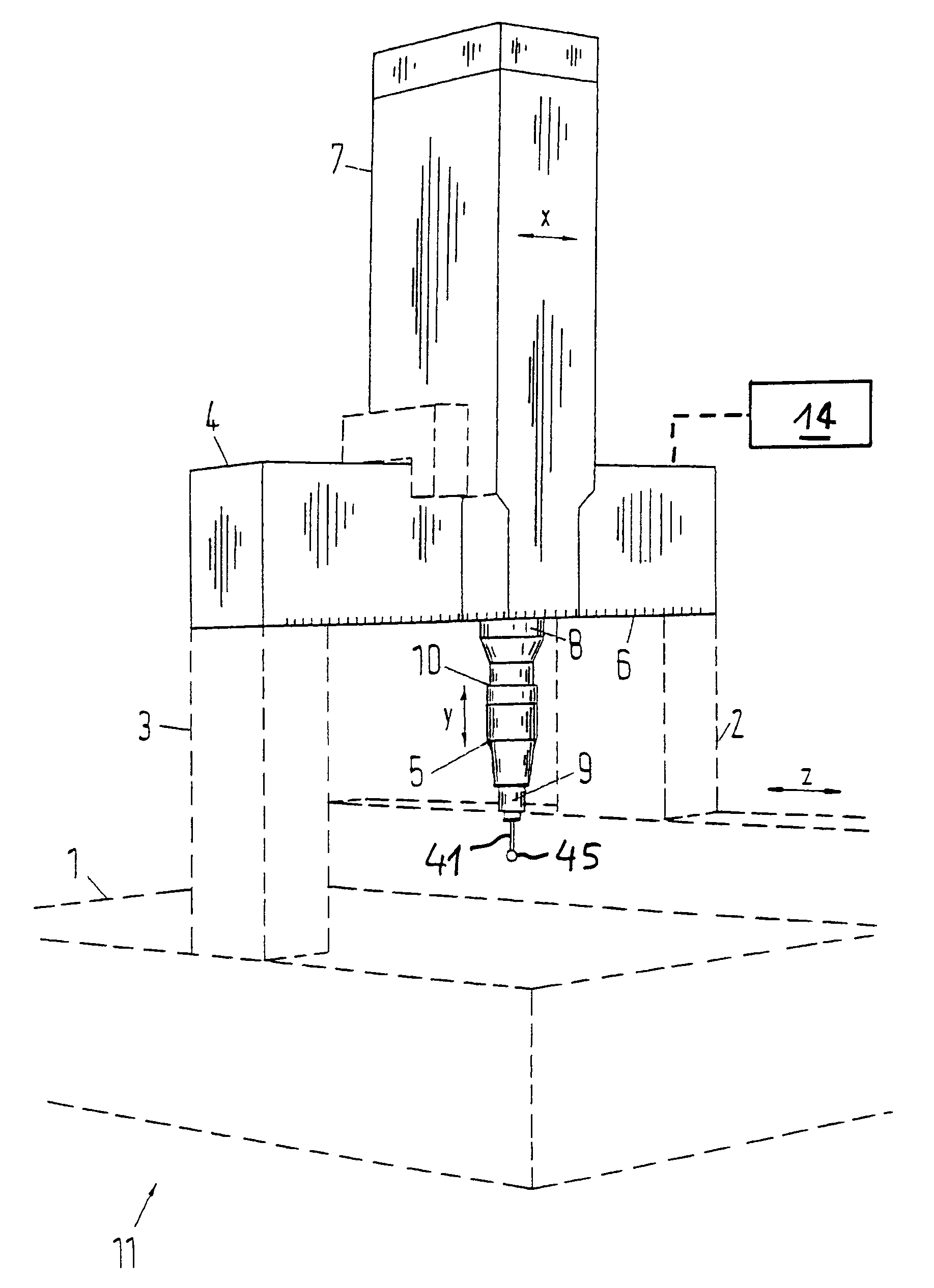
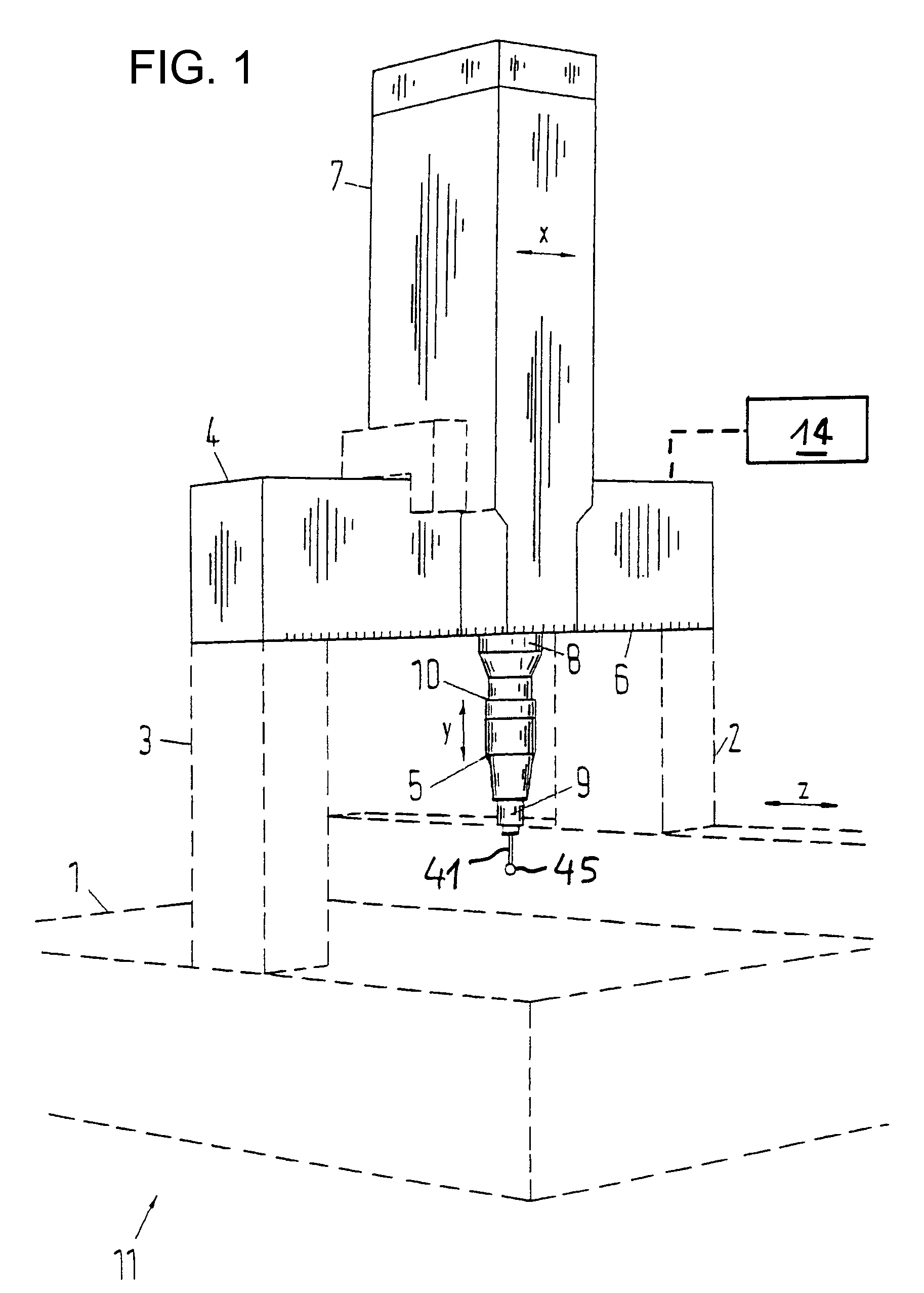
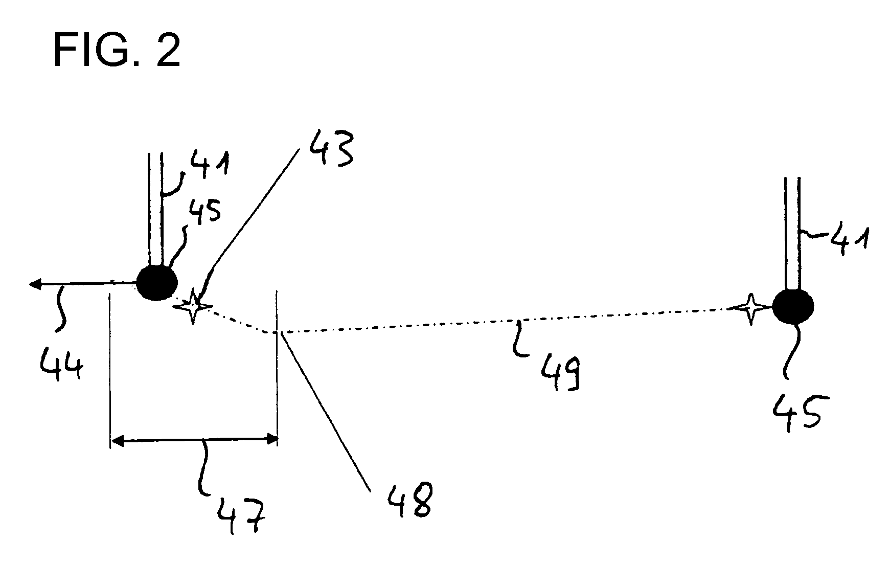
[0027]The coordinate measuring instrument 11 shown in FIG. 1 is of the type constructed in an overhead manner. The gantry is formed by two supports 2, 3 projecting upward and by a cross beam 4 which rests on the supports 2, 3 at its opposite ends. The supports 2, 3 can be moved in the z-direction along a measuring table 1 of the instrument. In addition, the instrument 11 has a center 7 which is movable in the x-direction along the longitudinal axis of the cross beam 4. At the bottom end of the center 7, a holder 8 of the center 7 carries a sensor 5 which is connected to the carrier 8 by means of a detachable coupling 10. The sensor 5 includes the measuring systems of the instrument, by way of which a deflection of a feeler 41 can be measured when said feeler senses a workpiece with its sensing ball 45. The carrier 8 with the parts 5, 41 fastened thereon is movable in the y-direction, wherein the z-direction, the x-direction and y-direction are perpendicular to each other in pairs su...


PUM


Abstract

A method for operating a coordinate measuring machine or a machine tool. A movement of a machining part is controlled in such a way that, during the movement of the machine part, a predetermined maximum acceleration and/or a predetermined maximum jerk is not exceeded. The maximum acceleration and/or the maximum jerk is varied depending on the position of the machine part and/or depending on the alignment of the machine part.

Description

BACKGROUND OF THE INVENTIONField of the Invention[0001]The invention relates to a method for operating a coordinate measuring machine or a machine tool. The invention also relates to such a machine.[0002]These types of machines have moveable machine parts, in many cases a tool being arranged on an arm of the machine (e.g. a center or a horizontally aligned arm). The tool can be a machining tool for machining a workpiece (in the case of the machine tool) or a sensing tool for sensing the surface of a tool (in the case of a coordinate measuring machine). Instead of the term coordinate measuring machine, the term coordinate measuring instrument is frequently also used. The measuring tool is, for example, a feeler, at the free end of which a sensing body (e.g. a sensing ball) is arranged, by way of which the surface of the workpiece is sensed. In this case, the position of the sensing body, in which it senses the surface of the workpiece, is determined from the measuring system of the m...

Claims


Application Information

Patent Timeline
Patent Type & Authority Patents(United States)
IPC IPC(8): G06F19/00G01B5/008G01B21/04
CPCG01B5/008G01B21/047
Inventor SCHON, HENNINGBURGER, JOCHENGRUPP, GUENTERRUCK, OTTOAUBELE, EUGENBERNHARDT, RALF
Owner CARL ZEISS IND MESSTECHN GMBH
Why Eureka
Try Eureka