
Machining power supply device for electric discharge machine

Active Publication Date: 2019-03-05
FANUC CORP
View PDF21 Cites 0 Cited by
  • Summary
  • Abstract
  • Description
  • Claims
  • Application Information

AI Technical Summary

Benefits of technology

The present invention is a machining power supply device for an electric discharge machine. The device can prevent variation in the charged voltage across a capacitor without reducing the machining speed. This allows for more stable and efficient machining.

Problems solved by technology

This approach, however, increases the time taken for charging the capacitor C, leading to reduction of the machining speed.

Method used


Image

  • Machining power supply device for electric discharge machine
  • Machining power supply device for electric discharge machine
  • Machining power supply device for electric discharge machine

Examples


Embodiment Construction

[0030]Hereinafter, the same or similar components and structures as those in the conventional techniques are denoted by the same reference characters.

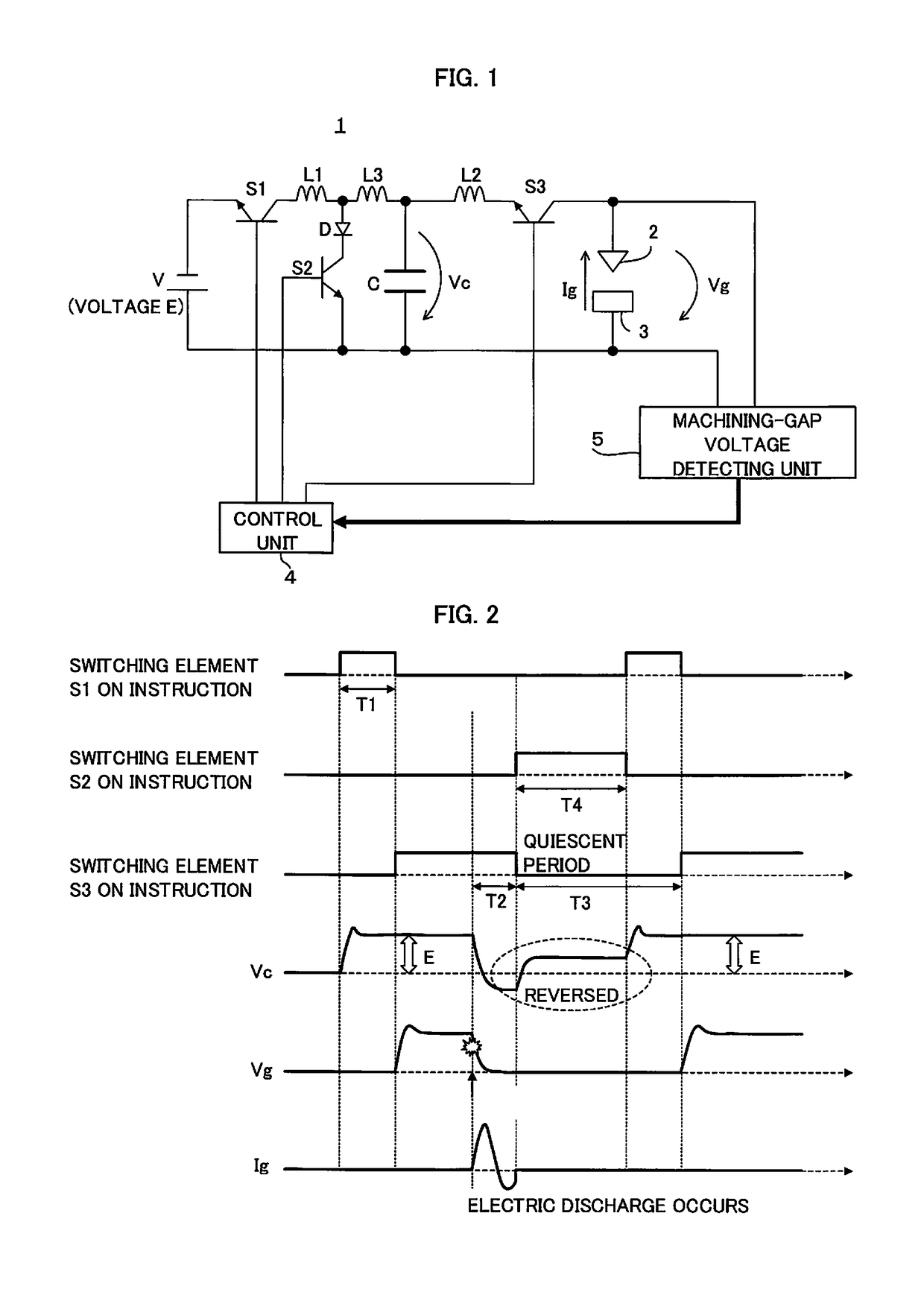
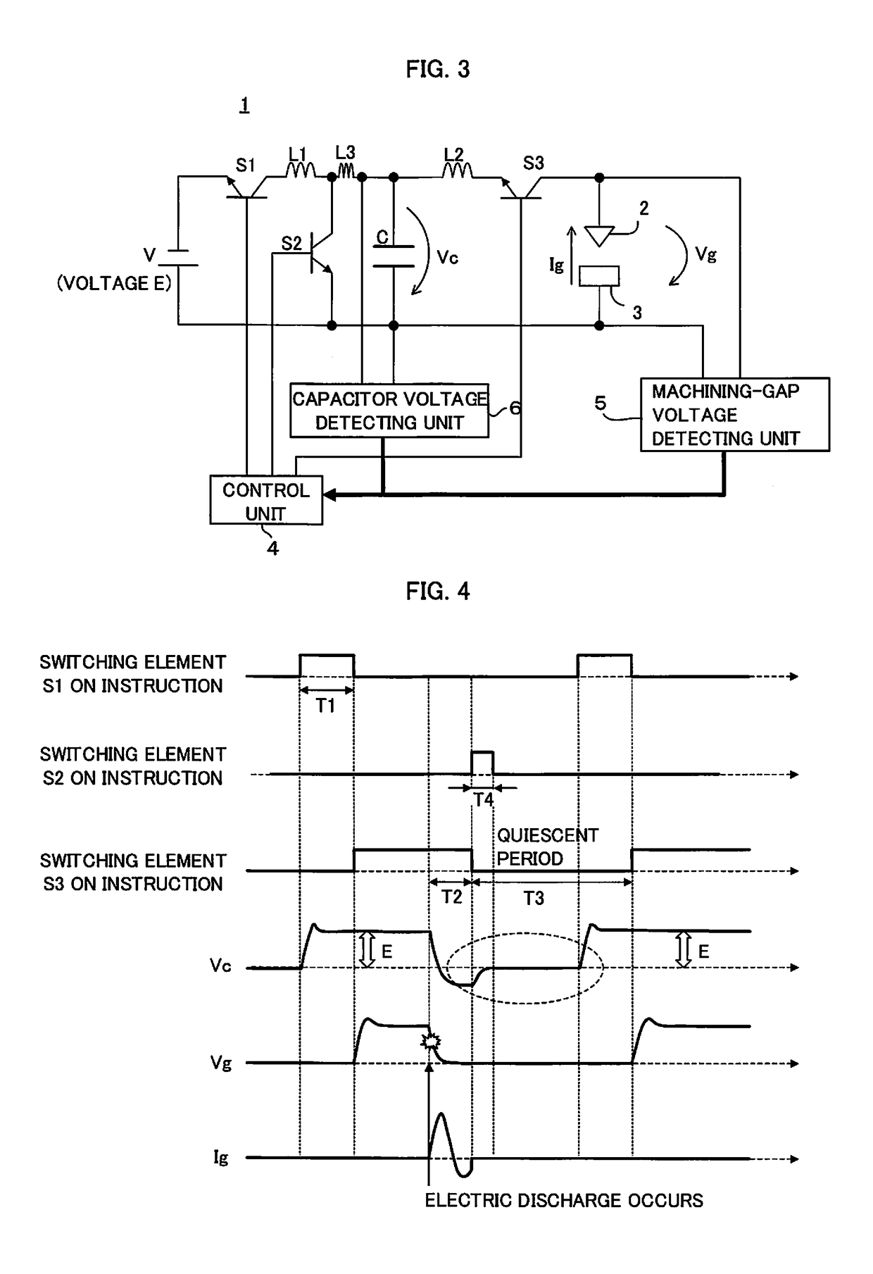
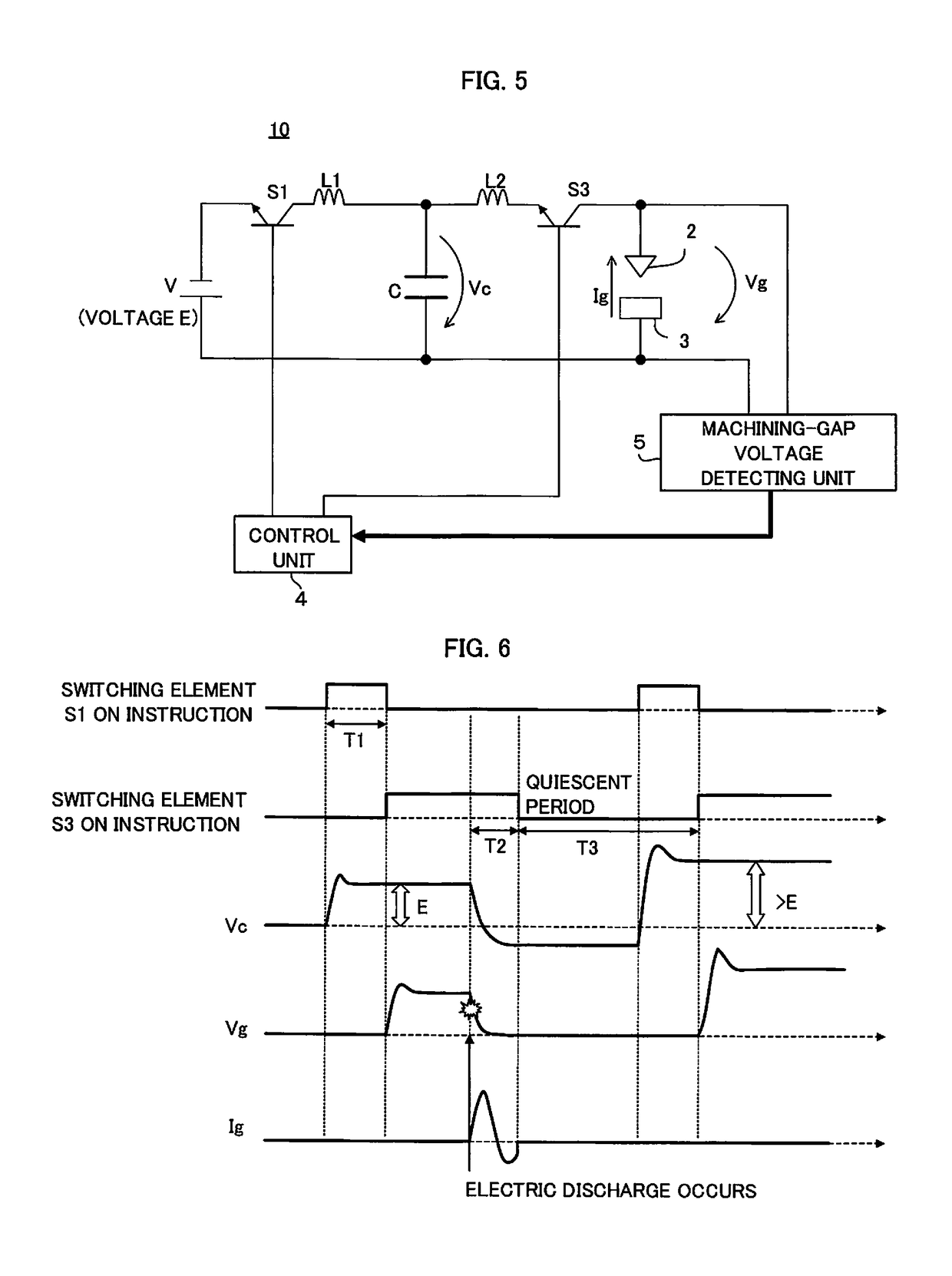
[0031]FIG. 1 shows an embodiment of a machining power supply device for an electric discharge machine according to the present invention. Examples of the electric discharge machine include a wire electric discharge machine and a die sinking electric discharge machine. The machining power supply device 1 is a power supply device for an electric discharge machine which performs electric discharge machining of a workpiece 3 by applying a voltage to a machining gap between an electrode 2 and the workpiece 3. The machining power supply device 1 for the electric discharge machine includes a DC voltage source V (voltage E), a first semiconductor switching element S1, a second semiconductor switching element S2, a third semiconductor switching element S3, a capacitor C, a rectifier element D, a machining-gap voltage detecting unit 5, and a con...


PUM

PropertyMeasurementUnit
Timeaaaaaaaaaa
Electric potential / voltageaaaaaaaaaa

Abstract

A machining power supply device for an electric discharge machine performs control to turn on a first semiconductor switching element, which is arranged in series between a DC power supply and a capacitor connected in parallel with a machining gap between an electrode and a workpiece, to charge the capacitor, and turn on a second semiconductor switching element, which is arranged in parallel with the capacitor and connected to a rectifier element, within a period in which the first semiconductor switching element is off.

Description

RELATED APPLICATIONS[0001]The present application claims priority to Japanese Application No. 2014-094293, filed Apr. 30, 2014, the disclosure of which is hereby incorporated by reference herein in its entirety.BACKGROUND OF THE INVENTION[0002]Field of the Invention[0003]The present invention relates to a machining power supply device for an electric discharge machine which machines a workpiece into a desired shape by changing the relative positions of the workpiece and an electrode by a servomotor while applying a voltage to the machining gap between the electrode and the workpiece to cause an electric discharge across the gap.[0004]Description of the Related Art[0005]In electric discharge machining, rough machining and finish machining are used for different purposes. In the rough machining, the energy of a single discharge is increased to do high-speed processing. In the finish machining, the energy of a single discharge is decreased to do high-precision processing. For the finis...

Claims


Application Information

Patent Timeline
IPC IPC(8): B23H1/02B23H7/14
CPCB23H1/022B23H1/02B23H7/14B23H2300/22B23H2300/20
Inventor NAKASHIMA, YASUOKAWAHARA, AKIYOSHI
Owner FANUC CORP
Learn More