System for controlling electrical power generated by a permanent magnet machine

a permanent magnet machine and electrical power technology, applied in power conversion systems, electric generator control, electrical apparatus, etc., can solve the problems of damage to the ecu, inability to actively control, and inability to directly control by deactivating the mosfets

Active Publication Date: 2021-09-23
SEDEMAC MECHATRONICS PVT
View PDF0 Cites 0 Cited by
  • Summary
  • Abstract
  • Description
  • Claims
  • Application Information

AI Technical Summary

Benefits of technology

[0009]In an embodiment, the present invention provides a system for controlling electrical power generated by a permanent magnet machine, the permanent magnet machine coupled to an internal combustion engine, the system comprising a central processing unit configured to, determine speed of the machine, and compare the machine speed with a predetermined range of machine speeds, a series power switching circuit connected between the machine and a battery, a bus decoupling power switch connected between a voltage bus and the battery, and a bridge switching circuit connected between the voltage bus and the machine, the bridge switching circuit configured to amplify voltage generated by the machine if the machine speed is less than a predetermined value or fall within a predetermined range thereby charging the battery with amplified voltage even at lower machine speeds, wherein the central processing unit selectively connects the bridge switching circuit with the battery by actuating the bus decoupling switch and / or the series power switching circuit depending upon the machine speed.

Problems solved by technology

Since this rectification is a result of body diode of MOSFETs, it cannot be directly controlled by deactivating the MOSFETs.
In a permanent magnet machine, the back-emf generated at the machine terminals is proportional to speed of rotation of the machine, and cannot be actively controlled (for example by field excitation control).
Beyond a certain operation speed, the DC bus voltage crosses the safe operating voltage, which can damage the ECU.
While this operation ensures that DC bus voltage remains within permissible limits, it results in an inefficient power generation operation due to heating of stator coil and MOSFET bridge which is undesirable.
On the other hand, if machine characteristics are so chosen that the shunt-method of generation control is to be performed only at high operating speeds which are not experienced often in normal engine operation, then at low engine speeds the back-emf generated at machine terminals may not be enough to supply required power to battery and other electrical loads.
Further, the current required for cranking of engine is unduly increased.

Method used


Image

  • System for controlling electrical power generated by a permanent magnet machine
  • System for controlling electrical power generated by a permanent magnet machine
  • System for controlling electrical power generated by a permanent magnet machine

Examples


Embodiment Construction

[0023]The present invention relates to system for controlling operation of an integrated starter generator which can perform starting control and generation control such that shunt-method of generation control is required only at high operating speeds and sufficient electric power is generated at low operating speeds, while cranking current is not unduly increased.

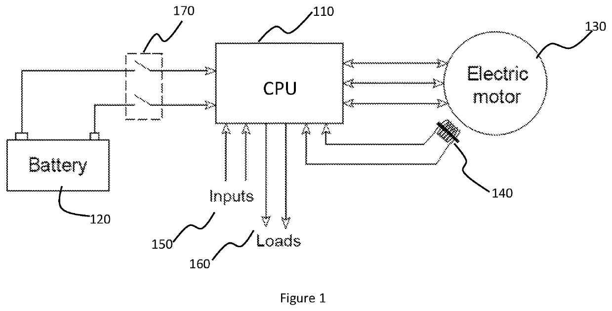
[0024]FIG. 1 shows a schematic diagram of a system in accordance with an embodiment of the present invention. A central processing unit (CPU) 110 is connected to the battery 120 and a polyphaser permanent magnet electric machine 130. The CPU receives input from an ignition trigger sensor and possibly from sensors used for sending the electric machine rotor position 140. The CPU also receives inputs from a set of other sensors and switches 150 which are used for overall control of the engine operation and ISG operation. Examples of such sensors are thermal sensor used for measurement of engine temperature and throttle posit...


PUM


Abstract

A system for controlling electrical power generated by a permanent magnet machine coupled to an internal combustion engine includes a central processing unit configured to determine speed of the machine, and compare the machine speed with a predetermined range of machine speeds, a series power switching circuit connected between the machine and a battery, a bus decoupling power switch connected between a voltage bus and the battery, and a bridge switching circuit connected between the voltage bus and the machine and configured to amplify voltage generated by the machine if the machine speed is less than a predetermined value or fall within a predetermined range thereby charging the battery with amplified voltage even at lower machine speed. The central processing unit selectively connects the bridge switching circuit with the battery by actuating the bus decoupling switch and/or the series power switching circuit depending upon the machine speed.

Description

FIELD OF THE INVENTION[0001]The present invention relates to a system for controlling electrical power generated by a permanent magnet machine coupled to an internal combustion engine.DESCRIPTION OF THE BACKGROUND ART[0002]For starting of an internal combustion (IC) engine, it needs to be rotated at a sufficiently high speed before the self-sustaining combustion process can commence. For this purpose, many conventional IC engines are equipped with an electric starter system. The electric starter system consists of an electric motor powered by a battery, the motor being connected to crankshaft of IC engine through a suitable power driving mechanism such as gear train. Further, a different electric machine coupled to the crankshaft is used to generate electric power required to charge the battery and power other electrical loads.[0003]In an integrated starter generator (ISG) system for IC engines, a single electric machine connected to crankshaft is used for both engine starting and e...

Claims


Application Information

Patent Timeline
Patent Type & Authority Applications(United States)
IPC IPC(8): H02P6/20H02M1/00H02P9/48
CPCH02P6/20H02P9/48H02M1/0085H02P9/44
Inventor DIXIT, AMITATHAVALE, ARVINDJOSHI, ANAYKUMAR
Owner SEDEMAC MECHATRONICS PVT
Why Eureka
Try Eureka