Motion Planning for a Conveyor System of a Servo Press Installation

a technology of servo press and conveyor system, which is applied in the direction of programme control, total factory control, extrusion control device, etc., can solve the problems of reducing correspondingly high peak power during forming, and increasing the time required for loading and unloading, so as to improve the operation of the servo press installation and reduce the maximum achievable machine speed

Pending Publication Date: 2020-03-19
SIEMENS AG
View PDF11 Cites 0 Cited by
  • Summary
  • Abstract
  • Description
  • Claims
  • Application Information

AI Technical Summary

Benefits of technology

[0009]In view of the foregoing, it is an object of the invention to provide an improved operation of a servo press installation, where it is necessary to reduce a maximum achievable machine speed to the least possible extent.

Problems solved by technology

This results in a correspondingly high peak power during the forming in the case of servo presses.
The slower the capability of the conveyor system to execute the transfer of material, the more time required for the loading and unloading on a press.
Correspondingly, the press must provide more time for this process, which can result in a slower pressing speed.
In consequence, the press must provide more time for this process which, in turn, may lead to bridling of the press.
This is disadvantageous, because this is precisely the phase in which the press might be operated at higher than average speed.

Method used


Image

  • Motion Planning for a Conveyor System of a Servo Press Installation
  • Motion Planning for a Conveyor System of a Servo Press Installation

Examples


Embodiment Construction

[0047]In the figures, functionally identical elements are identified by the same reference symbols, unless indicated otherwise.

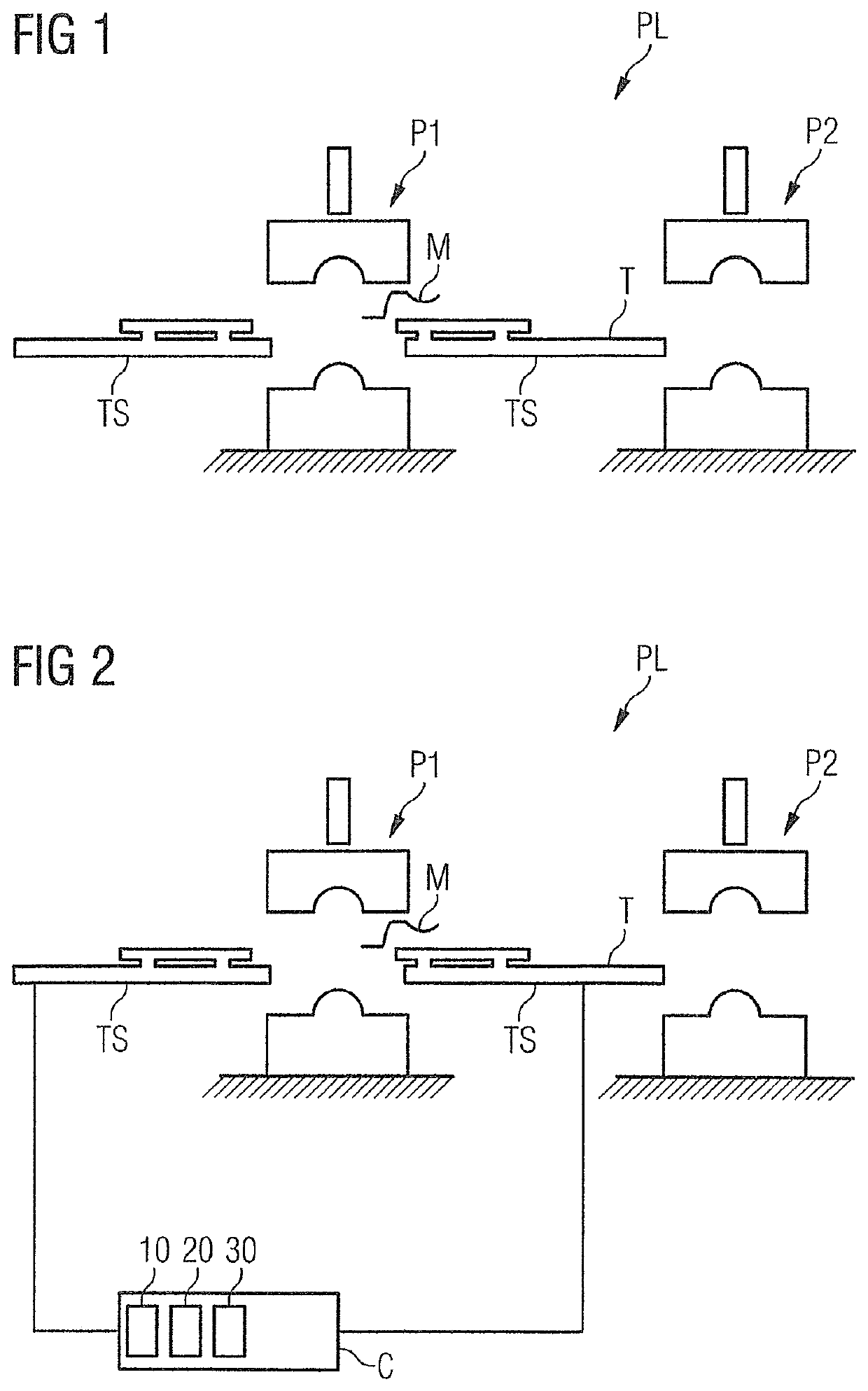
[0048]FIG. 1 shows a sketch of a servo press installation or press line or pressing line PL, in which a first servo press P1 and a second servo press P2 are located. In the interests of clarity, further servo presses have been omitted from this representation. Realistically, more than two servo presses are present in a conventional servo press installation. Moreover, a conveyor system TS is outlined, which incorporates a transfer apparatus T, also described as a transfer system. A transfer apparatus T of this type is configured with a geometry that is adapted to a servo press and incorporates, for example, a moveable part, which is arranged within the transfer apparatus T, and which is appropriate for the accommodation of a product M which is to be processed, such as a workpiece that is to be pressed. For example, a gripper, a gripper arm, a clamp or a sucke...


PUM

PropertyMeasurementUnit
timeaaaaaaaaaa
peak poweraaaaaaaaaa
constant-acceleration transitionaaaaaaaaaa

Abstract

A method for motion planning for a conveyor system of a servo press installation, a motion controller for a conveyor system of a servo press installation, and to an associated computer program product, wherein an angular offset is optimized with respect to power peaks.

Description

BACKGROUND OF THE INVENTION1. Field of the Invention[0001]The invention relates to motion planning for a conveyor system of a servo press installation, a motion controller for a conveyor system of a servo press installation, and to an associated computer program product.2. Description of the Related Art[0002]In the forming industry, presses are employed for the forming or pressing of material. In many cases, entire press lines are employed, in which a plurality of presses are arranged one after another, and a workpiece or product that is to be processed is moved from one press to the next, or to subsequent presses. For example, a metal part to be pressed is firstly pressed into a first shape by a first press, and is then transferred to a second press as a second processing station, where the metal part is subject to further processing. These presses are partially independent and, for process engineering purposes, they are connected by systems for the conveyance of material. Referenc...

Claims


Application Information

Patent Timeline
Patent Type & Authority Applications(United States)
IPC IPC(8): B21D43/12B21C31/00
CPCB21D43/12B21C31/00B65G43/00B65G47/90B65G47/91G05B19/41815G05B2219/31078Y02P90/02B65G65/005
Inventor BITTEROLF, DAVIDHOJA, STEPHANKNEISSL, DOMINIKSCHLEGEL, OLEGSTÖCKEL, TINA
Owner SIEMENS AG
Why Eureka
Try Eureka