Rotary hot tool and heat ablation apparatus using the same

a technology of hot tool and hot tool, which is applied in the direction of auxillary shaping apparatus, butchering, and butter production, etc., can solve the problems of increasing the time required to machine the workpiece, increasing the surface roughness of the workpiece and the machining accuracy of the hot tool, and deteriorating the working conditions of chips and dust. , to achieve the effect of reducing the machining speed and deteriorating the machining accuracy

Active Publication Date: 2007-02-01
KOREA ADVANCED INST OF SCI & TECH
View PDF4 Cites 4 Cited by
  • Summary
  • Abstract
  • Description
  • Claims
  • Application Information

AI Technical Summary

Benefits of technology

[0011] Accordingly, the present invention has been made keeping in mind the above problems occurring in the prior art, and an object of the present invention is to provide a rotary hot tool which solves problems of deterioration of machining accuracy and reduction in machining speed due to molten polymer, and a heat ablation apparatus using the same.

Problems solved by technology

These chips and dust deteriorate working conditions.
Thus, the effective machining range, in which the workpiece is substantially pyrolyzed, is too narrow and, consequently, the time required to machine the workpiece is increased.
Therefore, if this hot tool is used in a preliminary machining stage in which a relatively large surface area must be machined, only a small part of the workpiece is pyrolyzed, and most of the remaining part merely enters a molten state and may undesirably adhere to the workpiece or the hot tool, thus increasing surface roughness of the workpiece and the machining accuracy of the hot tool.
However, this patent has a disadvantage in that only when the hot tool moves in a longitudinal direction can molten polymer be removed during a machining process.
Furthermore, because the hot tool must be heated to a high temperature to rapidly pyrolyze the polymer in the receiving spaces 24, it is very difficult to precisely machine the workpiece made of foam material.

Method used


Image

  • Rotary hot tool and heat ablation apparatus using the same
  • Rotary hot tool and heat ablation apparatus using the same
  • Rotary hot tool and heat ablation apparatus using the same

Examples


Embodiment Construction

[0022] Hereinafter, a preferred embodiment of the present invention will be described in detail with reference to the attached drawings.

[0023]FIG. 3 is an exploded perspective view showing an embodiment of a rotary hot tool 100 according to the present invention. FIG. 4 is an exploded perspective view showing a rotary unit 120 of the rotary hot tool 100 of FIG. 3.

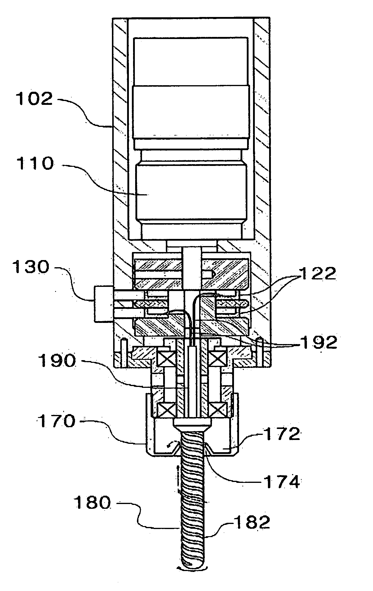
[0024] As shown in FIG. 3, the rotary hot tool 100 includes a casing 102, a motor 110, the rotary unit 120, an electrode terminal 130, a holder 150, a polymer storage case 170 and a heating body 180.

[0025] The casing 102 has two receiving chambers 102a which are separated from each other. The motor 110 and the rotary unit 120 are provided in the respective receiving chambers 102a. Insertion slots 102b, which communicate with the lower receiving chamber 102a, are formed through a sidewall of the casing 102. The electrode terminal 130 is inserted into the insertion slots 102b.

[0026] As shown in FIG. 4, the rotary unit 120...


PUM

PropertyMeasurementUnit
resistanceaaaaaaaaaa
speedaaaaaaaaaa
voltageaaaaaaaaaa

Abstract

Disclosed herein is a hot tool which machines a workpiece made of foam material. The hot tool of the present invention includes a motor, a rotary unit which is coupled to the motor, and an electrode terminal which is connected to an outside power supply and contacts an electrode of the rotary unit. The hot tool further includes a heating body which is coupled to the rotary unit so that the heating body is heated by electric current supplied through the electrode terminal, with a spiral groove formed in a circumferential outer surface of the heating body. The hot tool further includes a polymer storage case which is provided at an upper position on the circumferential outer surface of the heating body, so that molten polymer that moves along the spiral groove is stored in the polymer storage case. Therefore, the hot tool of the present invention has increased machining accuracy and prevents a workshop from becoming messy due to molten polymer.

Description

BACKGROUND OF THE INVENTION [0001] 1. Field of the Invention [0002] The present invention relates generally to hot tools to machine workpieces made of foam material and heat ablation apparatuses using the same and, more particularly, to a hot tool having enhanced machining accuracy and minimally discharging pollutants, and a heat ablation apparatus using the same. [0003] 2. Description of the Related Art [0004] As well known to those skilled in the art, the manufacture of three-dimensional shapes from foam materials has been widely implemented in mold industries, test product manufacturing industries and design industries. Tools to machine workpieces made of foam material were proposed in U.S. Pat. No. 6,234,725, Korean Patent Application No. 2003-47255 and Korean Patent Application No. 2004-16967. [0005] The tool of U.S. Pat. No. 6,234,725 is a type that cuts foam. Because this type of tool machines foam by cutting it, chips and dust are generated during a machining process. These ...

Claims


Application Information

Patent Timeline
Patent Type & Authority Applications(United States)
IPC IPC(8): B29C67/00
CPCB23C1/06B23C3/00B29C44/5636B23P25/003B26F3/08B23C2226/61
Inventor YANG, DONG YOLSHIN, HA YONGKIM, HYO CHANLEE, SANG HO
Owner KOREA ADVANCED INST OF SCI & TECH
Why Eureka
Try Eureka