Blade for a helicopter Anti-torque device

a technology for anti-torque devices and blades, which is applied in the direction of propellers, propulsive elements, water-acting propulsive elements, etc., can solve the problems of unsuitable blades presenting geometrical shapes and unsuitable anti-torque devices, and the anti-torque device including such blades and such an arrangement of vanes is not capable of significantly improving its performance, so as to reduce the monopole noise, “thickness” noise, large variation chord

Active Publication Date: 2012-08-02
EUROCOPTER
View PDF6 Cites 55 Cited by
  • Summary
  • Abstract
  • Description
  • Claims
  • Application Information

AI Technical Summary

Benefits of technology

[0054]A blade in accordance with the invention also makes it possible to reduce the monopole noise (so-called “thickness” noise) due to the large variation in chord at the end. This variation in chord generates a modification in the sound signals emitted by each section of the blade. Consequently the sound signals are different for each section of the blade. This prevents the sound waves as received by a far observer from adding together effectively. Furthermore, this variation in chord at the end of the blade does not increase the thickness noise insofar as said large chord is compensated at the end by a smaller relative thickness. In this respect, a real thickness is conserved that is equivalent to the thickness of a blade having a rectangular shape in plan view, in spite of the increase in chord towards the end.
[0055]Another advantage of the blade in accordance with the invention lies in a reduction of interaction noise between the rotor blades and the stator guide vanes (so-called “dipolar” noise or “load” noise). The trailing edges of the blades that are curved in the above-specified direction prevent the vortex sheet from a blade striking a stationary vane in parallel manner. The curved trailing edge gives rise to a phase shift in the soundwaves received by a far observer and thus contributes to reducing the noise received by said observer.
[0056]Another advantage of the blade in accordance with the invention lies in a reduction in trailing edge noise (interaction between parietal pressure fluctuations and the trailing edge) as a result of the curved shape of said trailing edge. The three-dimensional effects generated by the curved trailing edge that is curved in the above-specified direction serves to compensate the wake deficit observed at the trailing edge (said deficit corresponding to a reduction in the flow speed of the air downstream from the trailing edge due to the presence of the blade in the flow), thereby reducing the trailing edge noise that presents a broadband frequency characteristic. Compensating the wake deficit also prevents turbulent elements becoming correlated, thereby reducing the impact of the rotor wake on the stator vanes and consequently enabling tonal noise to be reduced (i.e. the noise produced by frequency harmonics that are correlated with the speed of rotation and the number of blades of the rotor).
[0057]In other words, since the blade has a geometrical shape that is generally curved, the turbulent wake from said blade is likewise curved. Thus, when the wake from the blade meets a guide vane, the wake does not strike said vane in parallel. This also makes it possible to reduce the noise that is perceived.
[0058]Another advantage of the blade in accordance with the invention lies in the improvement in the general performance of said blade. For given lift, such a blade makes it possible to reduce the peripheral speed of the rotor. Such a reduction in peripheral speed gives rise to a systematic reduction in the amounts of noise generated by all of the noise sources of the rotor.
[0059]Another advantage of the blade in accordance with the invention lies in an angular phase offset between the leading edge and the trailing edge at the end of the blade. The increase in chord at the end of the blade in combination with the curved shape of the stacking line makes it possible to obtain different sweeps between the leading edge and the trailing edge. This produces a phase offset in the soundwaves in the event of any interaction between a blade and the turbulence generated by the preceding blades. The perceived noise is thus diminished.

Problems solved by technology

An anti-torque device including such blades and such an arrangement of vanes is not capable of significantly improving its performance in order to approach the performance of a conventional anti-torque rotor.
A blade presenting such a geometrical shape nevertheless appears to be unsuitable for improving the performance of a ducted anti-torque device.
The corrugations also increase the stiffness of the blades.

Method used


Image

  • Blade for a helicopter Anti-torque device
  • Blade for a helicopter Anti-torque device
  • Blade for a helicopter Anti-torque device

Examples


Embodiment Construction

[0065]Elements that are structurally and functionally identical and present in more than one of the figures are given the same numerical or alphanumerical reference in each of them.

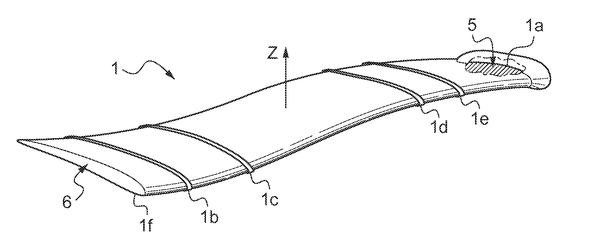
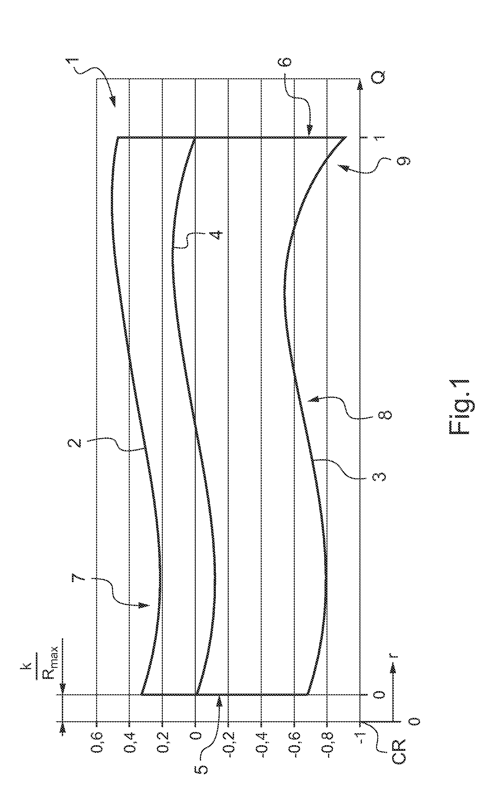
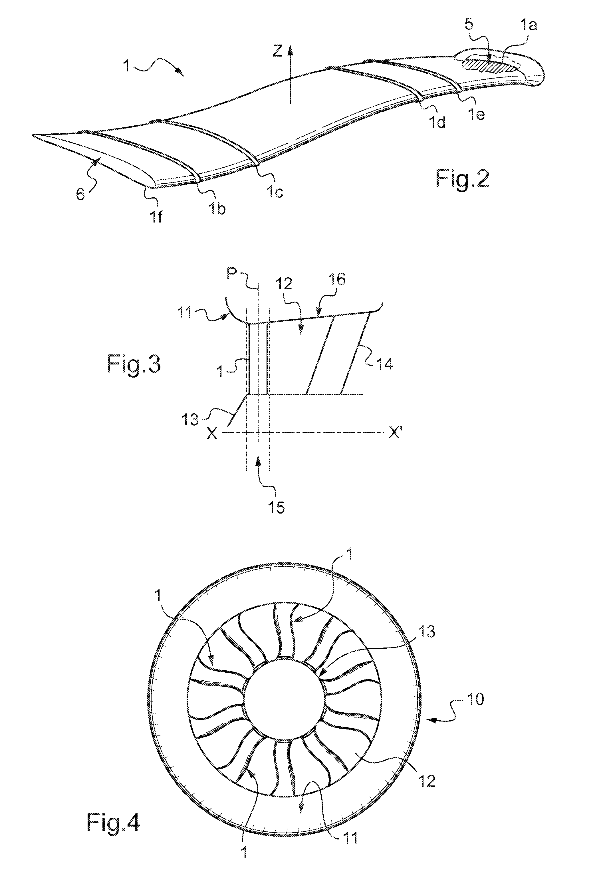
[0066]The objects given to the invention are achieved with the help of a blade 1 for a tail anti-torque device of a helicopter. The blade 1, shown diagrammatically in FIG. 1, by way of example, comprises an assembly of airfoil profile sections and presents a leading edge 2 and a trailing edge 3. More precisely, FIG. 1 shows a blade 1 prior to twisting relative to a line of twist 4 in compliance with a predetermined twisting relationship, and as a result it presents a plane extension surface defined firstly between the leading edge 2 and the trailing edge 3 of the airfoil profile sections, and secondly between the root section 5 and the end section 6 having respective airfoil profiles 1a and 1f (FIG. 2). In other words, this plane extension surface corresponds substantially to the plane defined by the chor...


PUM


Abstract

A blade (1) for a tail anti-torque device of a helicopter, said device comprising a ducted rotor (13). The blade (1) has an assembly of sections, a leading edge (2) and a trailing edge (3); a stacking line (4) of the profiles extending at a distance lying in the range 25% to 50% of the chord (C). The stacking line (4) presents a shape that is curved having successively from the root (5) to the end (6) of the blade a back sweep, a forward sweep, and a last back sweep; and a chord (C) that becomes larger going towards the end (6) of the blade (1) over at least the end profile (1a).

Description

CROSS REFERENCE TO RELATED APPLICATIONS[0001]This application claims priority to French patent application FR 10 / 04891 filed on Dec. 15, 2010, the disclosure of which is incorporated in its entirety by reference herein.BACKGROUND OF THE INVENTION[0002](1) Field of the Invention[0003]The invention relates to the general technical field of anti-torque rotors for rotorcraft, in particular for helicopters. More precisely, the invention relates to the technical field of ducted tail rotor anti-torque devices with blades angularly distributed using phase modulation, and for use in helicopters, in particular. Such anti-torque devices differ from non-ducted, conventional anti-torque rotors that do not constitute the subject matter of the present invention.[0004]The invention relates in particular to the above-mentioned anti-torque devices, also known as “Fenestron®” devices, in which a flow-guiding stator with stationary airfoil profile vanes is located downstream from an anti-torque rotor i...

Claims


Application Information

Patent Timeline
Patent Type & Authority Applications(United States)
IPC IPC(8): B64C11/16
CPCB64C11/18B64C27/82B64C2027/8254Y10S416/05Y10S416/02
Inventor GERVAIS, MARCGRESLE, BENOITFINCK, SEBASTIENSUDRE, LAURENT
Owner EUROCOPTER
Why Eureka
Try Eureka