Sternum retractor device

a retractor device and sternum technology, applied in the field of surgical devices, can solve the problems of difficult to close the sternum, difficult to achieve the effect of avoiding risks, and avoiding refractory dysfunctions

Inactive Publication Date: 2009-10-15
FUTURA ENG
View PDF6 Cites 27 Cited by
  • Summary
  • Abstract
  • Description
  • Claims
  • Application Information

AI Technical Summary

Benefits of technology

[0015]Accordingly, it is an object of the present invention to provide a temporary sternum retractor device for use in postponing closure of the sternum after a cardiac surgical procedure, that enables problems concerning maintaining and controlling the extent of sternum divarication to be safely and efficiently overcome, while avoiding risks associated with conventional makeshift devices.

Problems solved by technology

These dysfunctions are often refractory to common resuscitation techniques (catecholamine infusion, diuretics, intra-aortic counterpulsation, and the like).
In such circumstances, it may prove unfeasible to close the sternum, especially when the cardiac dysfunction is associated with severe myocardial, pulmonary or mediastinal tissue oedema.
This is because the extrinsic compression exerted by the sternum further worsens the already strained cardiopulmonary function of the engorged and congested mediastinal organs, with potentially severe haemodynamic and respiratory consequences, that are sometimes even incompatible with survival.
These makeshift and sometimes rudimental retractor devices have often given rise to complications correlated with their stability, dimensions and the sturdiness of the materials used.
For instance, a syringe with its edges cut to the required shape may become sharp and, as a consequence, potentially traumatic for the surface of the right ventricle lying underneath.
In addition to the inadequacy of the materials, the devices used in the past to artificially divaricate the sternal stumps were simply inserted between the stumps without the opportunity to adjust the distance between them.
Although they are considered “lifesavers”, none of the retractor systems used to date have ever been validated by the competent authorities (FDA, CE, etc.).

Method used


Image

  • Sternum retractor device
  • Sternum retractor device
  • Sternum retractor device

Examples


Embodiment Construction

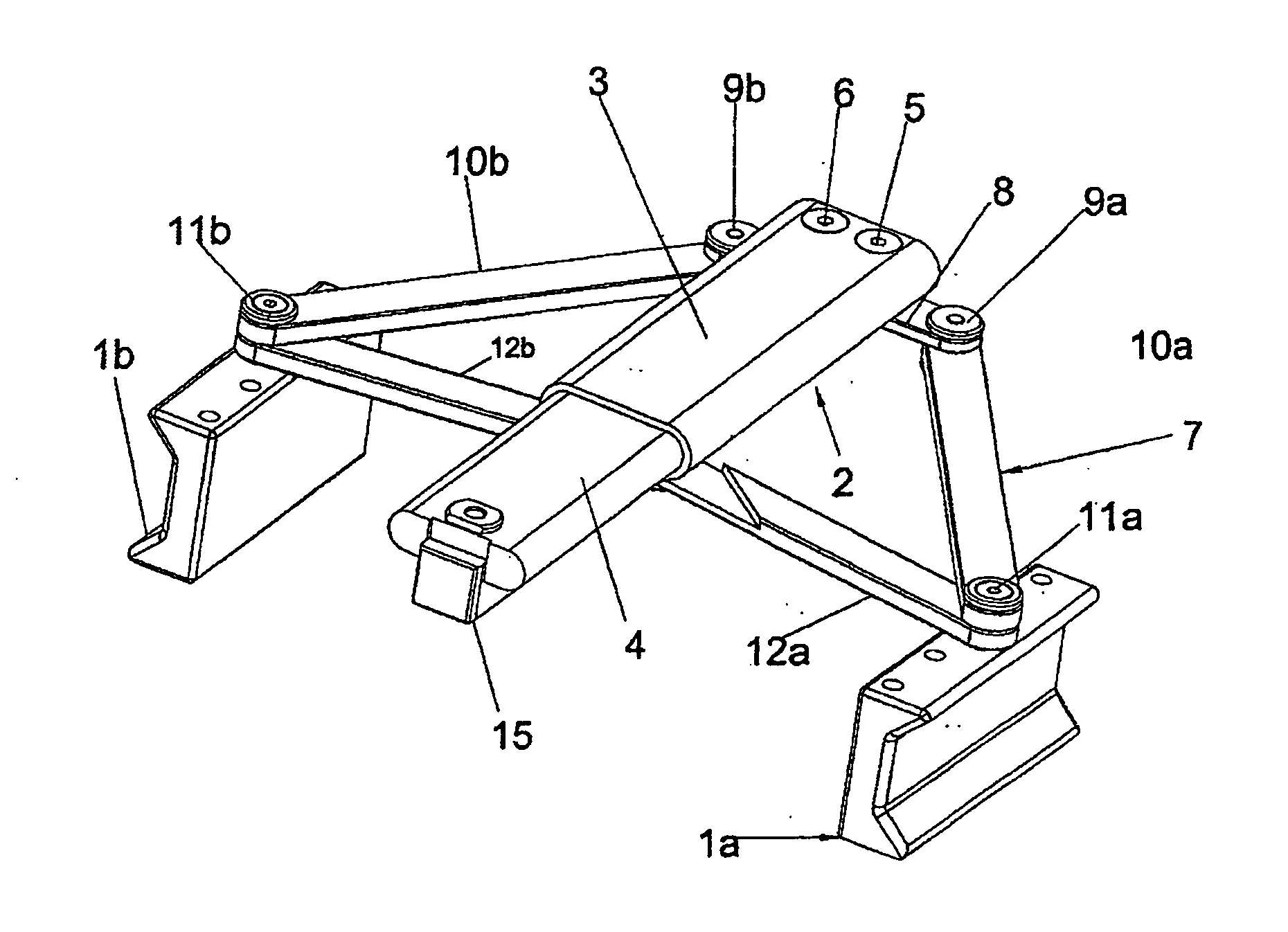
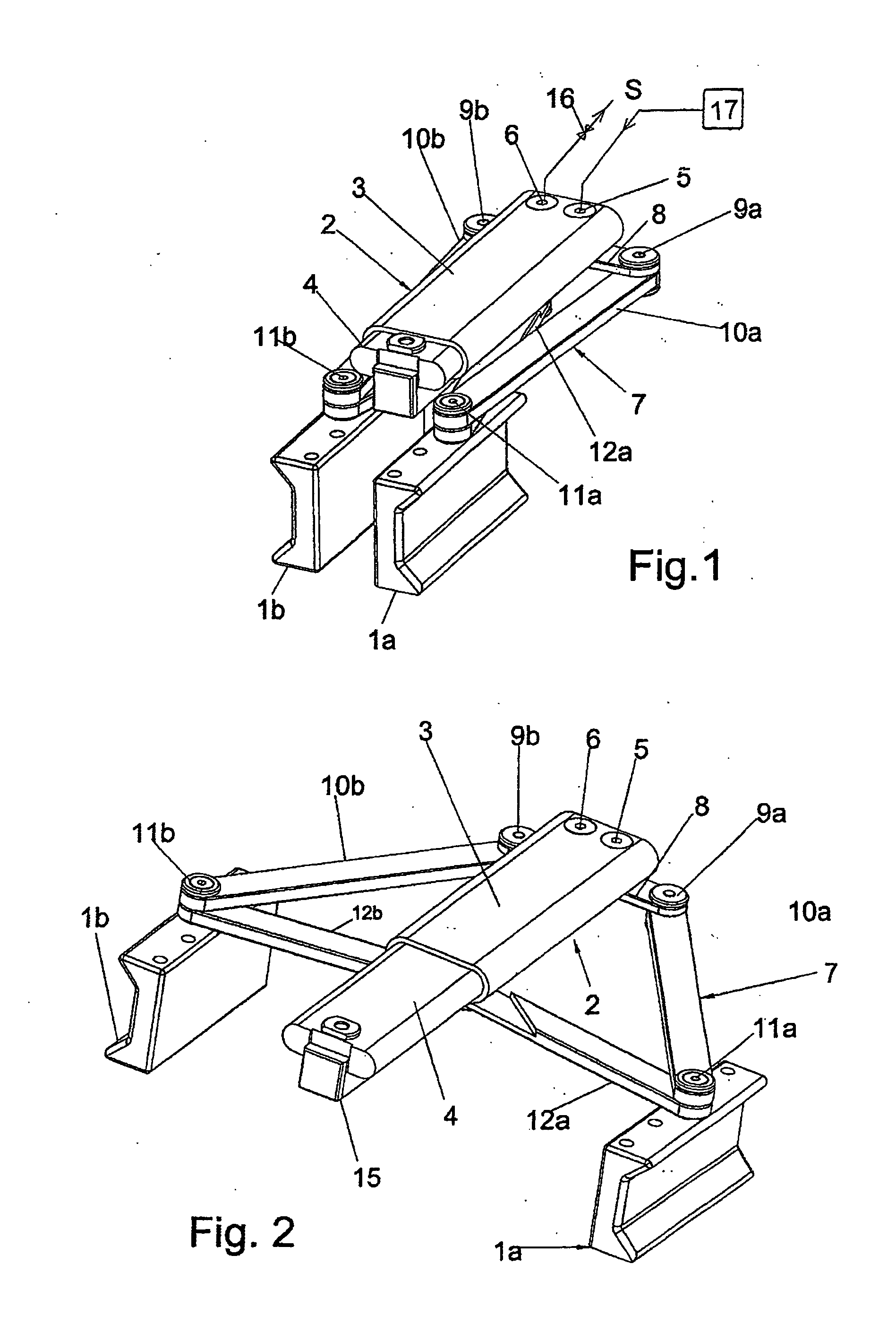
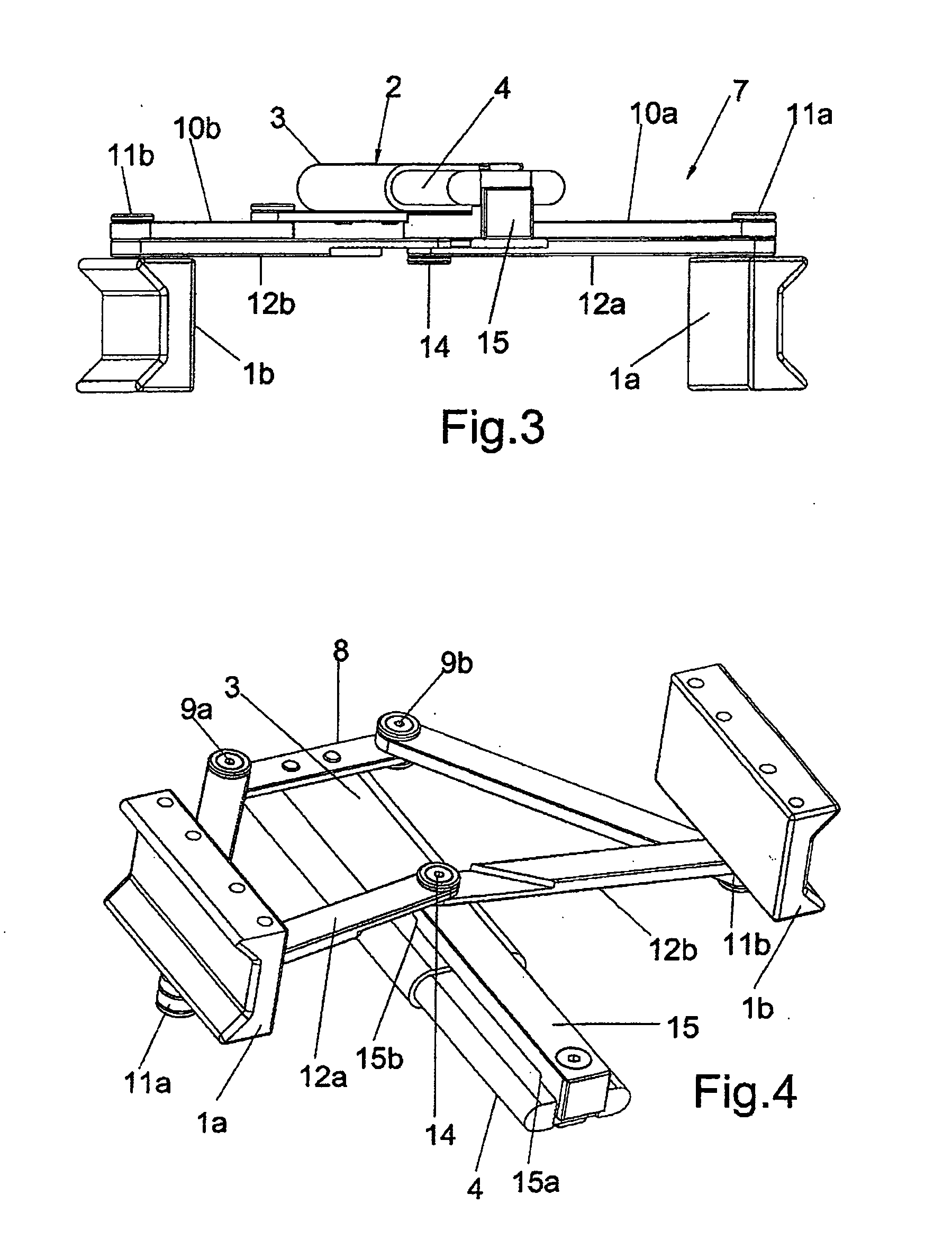
[0029]Referring now to the drawings and, more particularly, to FIGS. 1-8, there is shown generally a specific, illustrative sternum retractor device, according to various aspects of the present invention. In one embodiment, illustrated in FIG. 1, the device comprises a plurality, e.g., a pair, of relatively parallel, opposing jaws 1a, 1b, with a substantially U-shaped cross-section so as to house two sternal stumps and provide an abutment surface on which the force needed to keep them spread apart is applied. Jaws 1a, 1b are attached to an actuator device 2 which comprises a stationary part in the form of a tubular sleeve 3, closed at one end and having a very flat oval cross-section, in which a movable part in the form of a piston 4 is slidingly engaged in a watertight manner. An actuator fluid S is inserted in or extracted from the chamber inside sleeve 3, delimited by piston 4, through respective inlet and outlet ports 5 and 6 provided on the sleeve.

[0030]The tubular sleeve 3 lie...


PUM


Abstract

A sternum retractor device is disclosed suitable for temporarily maintaining a selected gap between two sternal stumps during cardiac surgical procedures. The device comprises a pair of jaws configured so as to be inserted between the stumps and shaped for firmly engaging the stumps, an actuator connected to the jaws for controlling their mutual closing and opening movements, and a member for controlled feed or withdrawal of a selected biocompatible actuator fluid in/from the actuator, thereby enabling the achievement and maintenance of the gap required between the stumps as well as the progressive reduction of the gap as a function of a patient's condition.

Description

FIELD OF THE INVENTION[0001]The present invention relates generally to surgical devices and, more particularly, to a device for use in cardiac surgical procedures or the like.BACKGROUND OF THE INVENTION[0002]During the final stages of cardiac surgical procedures, there may sometimes be prolonged periods of left and / or right ventricular dysfunction resulting from preoperative clinical conditions (e.g., ventricular function, bronchopneumonia, renal dysfunction) and / or lesions corresponding to the procedure underway (such as myocardial protection modalities, extracorporeal circulation, and / or intraoperative injuries). These dysfunctions are often refractory to common resuscitation techniques (catecholamine infusion, diuretics, intra-aortic counterpulsation, and the like).[0003]In such circumstances, it may prove unfeasible to close the sternum, especially when the cardiac dysfunction is associated with severe myocardial, pulmonary or mediastinal tissue oedema. This is because the extri...

Claims


Application Information

Patent Timeline
Patent Type & Authority Applications(United States)
IPC IPC(8): A61B1/32
CPCA61B17/02A61B2017/0237A61B2017/00991A61B2017/00539
Inventor BUCEFARI, MASSIMOSANTINI, FRANCESCO
Owner FUTURA ENG
Why Eureka
Try Eureka