Sheath With Radio-Opaque Markers For Identifying Split Propagation

a radio-opaque marker and sheath technology, applied in the field of delivery systems, can solve problems such as system straightening, inaccurate positioning, and perforation of the vessel wall

Inactive Publication Date: 2009-10-15
CAPPELLA INC
View PDF6 Cites 17 Cited by
  • Summary
  • Abstract
  • Description
  • Claims
  • Application Information

AI Technical Summary

Problems solved by technology

There have been, however, problems associated with these delivery systems.
This movement can lead to inaccurate positioning and, in some instances, possible perforation of the vessel wall by a protruding end of the stent.
As the wire is actuated, however, tension in the delivery system can cause the system to straighten.
This change of the geometry of the system within the anatomy can also lead to inaccurate stent positioning.
There is, ho

Method used


Image

  • Sheath With Radio-Opaque Markers For Identifying Split Propagation
  • Sheath With Radio-Opaque Markers For Identifying Split Propagation
  • Sheath With Radio-Opaque Markers For Identifying Split Propagation

Examples


Embodiment Construction

[0024]In known systems, once propagation of the rupturing of the sheath is initiated, the propagation will generally continue without interruption due to the force of balloon expansion and the force due to an emerging end of the self-expanding stent. As will be described below in more detail, embodiments of the present invention provide a mechanism for visualizing and confirming that the sheath has ruptured correctly and / or sufficiently.

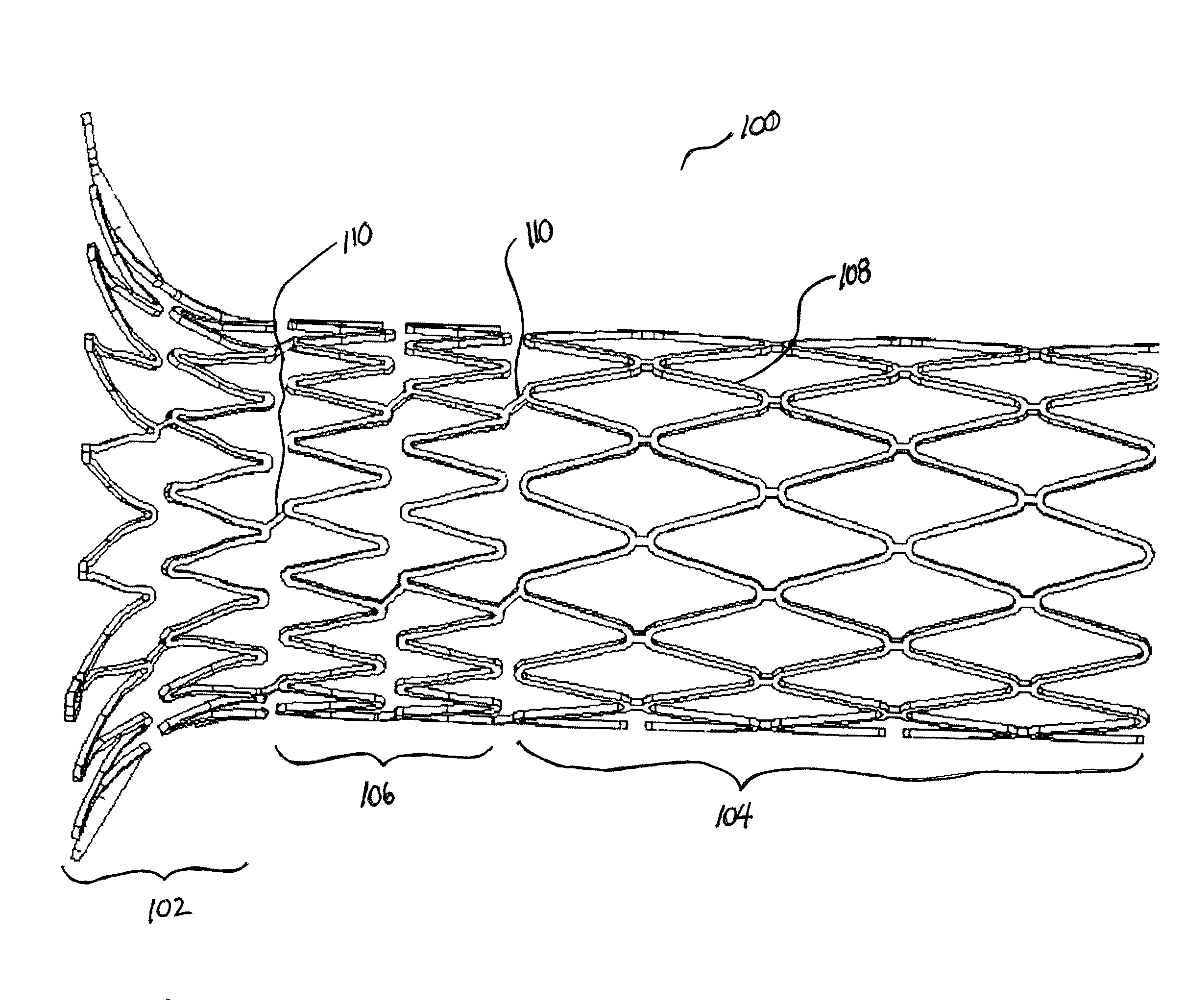
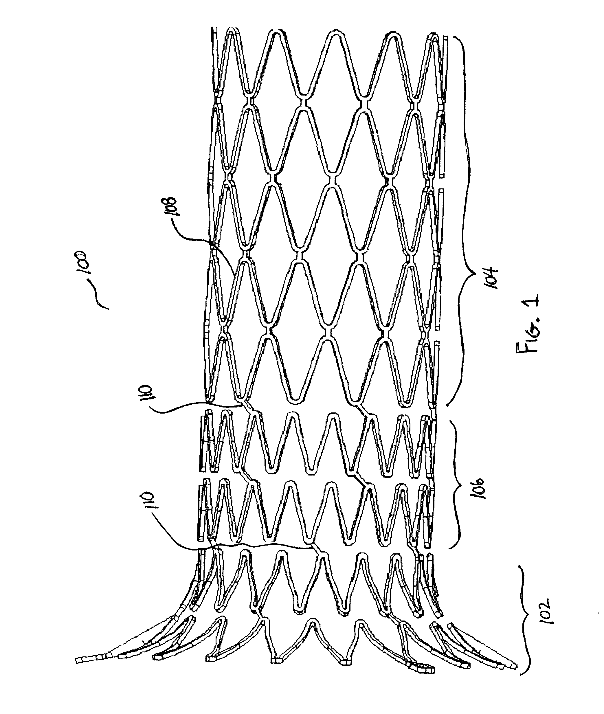
[0025]Reference is now made to FIG. 1, which illustrates a schematic view of a medical device 100, in this case, an ostial protection device as described in co-pending U.S. application Ser. No. 11 / 252,224 filed Oct. 17, 2005, and published as US2007-0061003 on Mar. 15, 2007, for “Segmented Ostial Protection Device,” and which is herein incorporated by reference in its entirety. It should be noted that while the present description refers to an ostial protection device, this is for purposes of explanation only. The claims, unless explicitly recited ot...


PUM


Abstract

A medical device delivery system includes a self-expanding medical device mounted on a balloon portion of a catheter. A sheath is provided around the medical device to hold the device in place with the device staying in a compressed state. The balloon portion is inflated to cause the sheath to rupture and release the self-expanding medical device. A number of radio-opaque markers in a pattern that will aid in determining whether or not the sheath has properly ruptured upon inflation of the balloon portion are provided on the sheath. The radio-opaque markers are positioned with respect to an expected sheath rupture propagation path along which the sheath is expected to rupture. The pattern of the markers changes as the sheath ruptures and this change is detected by an operator of the system.

Description

RELATED APPLICATIONSFIELD OF THE INVENTION[0001]The present invention relates to a delivery system for deployment of a medical device, e.g., a self-expanding vascular device such as a stent, in the vasculature of a patient. More particularly, a sheath has radio-opaque markings to aid in the visualization of sheath splitting progress during device delivery.BACKGROUND OF THE INVENTION[0002]Treatment of vascular blockages due to any one of a number of conditions can include balloon dilatation and treatment of an inner vessel wall by placement of a tubular prosthesis, e.g., a stent. The stent is positioned to prevent restenosis of the vessel walls after the dilatation. In some instances, a drug eluting stent is used to deliver medicine to the vessel wall to help reduce the occurrence of restenosis.[0003]Stents typically fall into two general categories of construction. The first category of stent is made from a material that is expandable upon application of a controlled force applied b...

Claims


Application Information

Patent Timeline
IPC IPC(8): A61F2/06A61F2/82
CPCA61F2/958A61F2/97A61F2250/0098A61F2002/9583A61F2002/821
Inventor OHRI, RACHITSTECKEL, MARK
Owner CAPPELLA INC
Why Eureka
Try Eureka