Method and apparatus for determining movement of an object in an imager

a technology of imager and object, applied in the direction of radiation beam directing means, medical science, diagnostics, etc., can solve problems such as the interpretation error of visualized images

Active Publication Date: 2012-12-04
GENERAL ELECTRIC CO
View PDF11 Cites 21 Cited by
  • Summary
  • Abstract
  • Description
  • Claims
  • Application Information

AI Technical Summary

Problems solved by technology

It is very common for the patient to move during the procedure, however, leading to inaccuracy in the projections of the 3D images into the radiographic images, or vice versa, which may lead to an interpretation error of the visualized images.

Method used


Image

  • Method and apparatus for determining movement of an object in an imager
  • Method and apparatus for determining movement of an object in an imager
  • Method and apparatus for determining movement of an object in an imager

Examples


Embodiment Construction

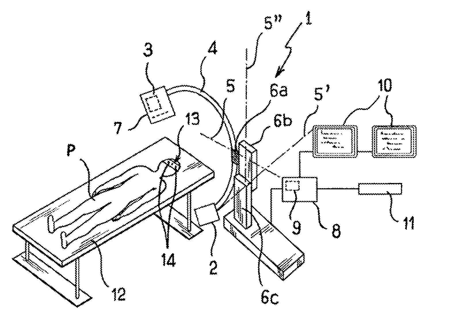
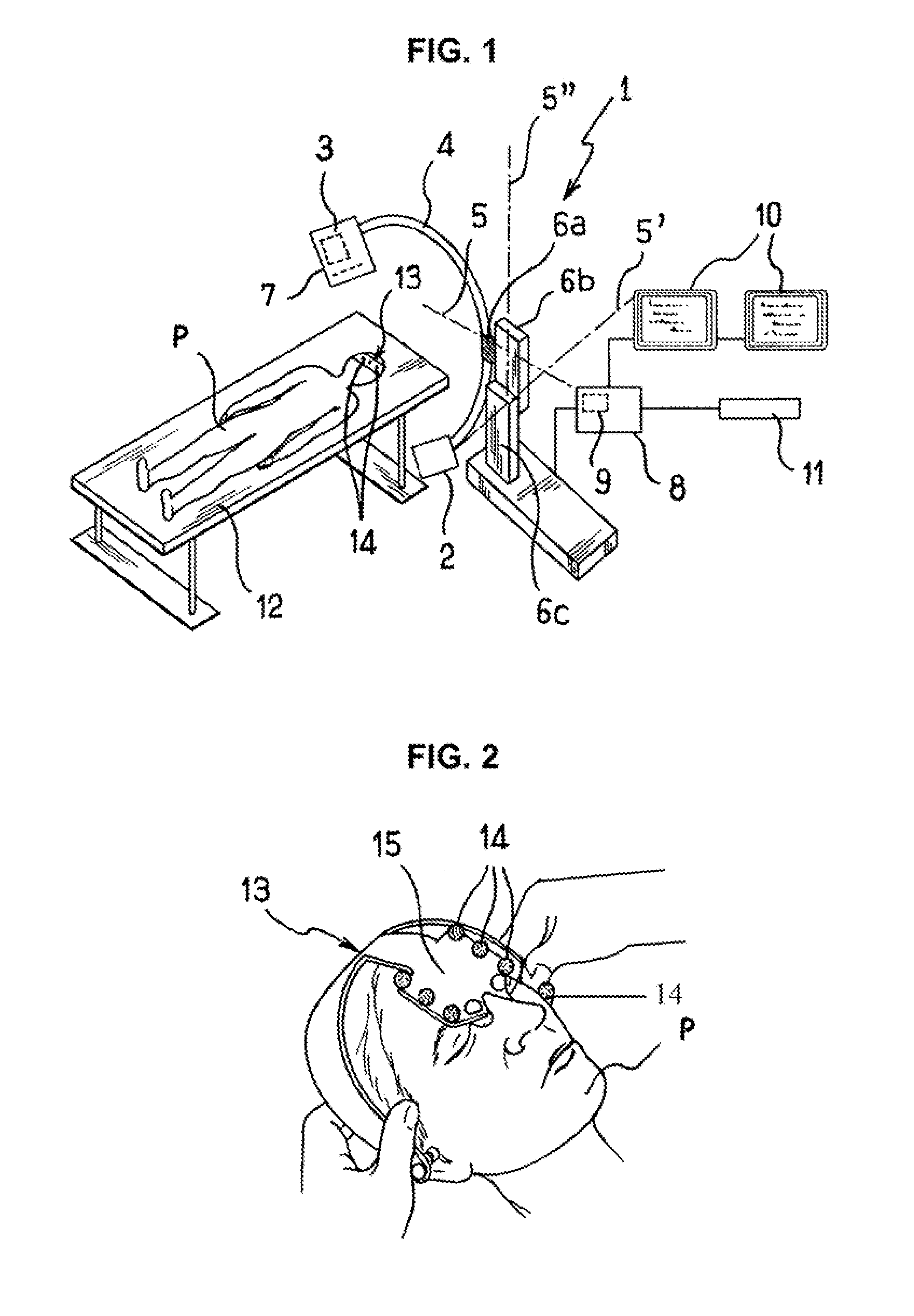
[0015]Referring to FIG. 1, an imaging apparatus 1 conventionally comprises means for receiving an image 2 (such as a digital image receiver), means for providing a radiation 3, such as X-ray, emitting radiation onto the means for receiving an image 2, the means for receiving an image 2 and the means for providing a radiation source 3 being respectively positioned at the end of a C-shaped or U-shaped arm 4. Arm 4 pivots about three axes 5, 5′ and 5″, which are schematically represented by dots and dashes. The C-shaped arm 4 pivots about an axis 5 secured to a carriage 6a that slides along an intermediate arm 6b. Intermediate arm 6b can pivot about a second axis 5′ perpendicular to a face of an L-shaped base 6c, which can pivot about a vertical axis 5″ by means of a rotary linkage. The C-shaped arm 4 can therefore pivot about three axes 5, 5′ and 5″, the axes forming a reference system for a specific position of the C-shaped arm 4. A position of the C-shaped arm 4 can thus be expresse...


PUM


Abstract

A method and apparatus for determining the three-dimensional movement of a patient positioned on a table between an X-ray source and an image receiver of an X-ray imaging apparatus is presented. The apparatus has an X-ray source positioned opposite an image receiver, the X-ray source and the image receiver being driven in rotation about an axis. The method and apparatus has the following operation: radio-opaque markers are placed on the patient's body; at least one first radiographic image of the patient is taken for a first determined fixed position of the imaging apparatus; at least one second radiographic image of the patient is taken for a second determined fixed position; and a matrix of the three-dimensional movement of the patient is determined on the basis of the two-dimensional movements of the markers in the radiographic images, the X-ray source constituting a fixed reference frame.

Description

CROSS-REFERENCE TO RELATED APPLICATIONS[0001]This application claims the benefit of a priority under 35 USC 119 (a)-(d) to French Patent Application No. 05 01741 filed Feb. 21, 2005, the entire contents of which are hereby incorporated by reference.BACKGROUND OF THE INVENTION[0002]An embodiment of the present invention relates to a method and apparatus for determining the movement of an object in an imager. In particular, an embodiment of the present invention relates to three-dimensional movement of a patient positioned on a table between a radiation source and an image receiver of an imaging apparatus.[0003]In the field of medical imaging, it is well known to use radio-opaque markers positioned on the object, such as a patient, as reference points in order to assist the guiding of surgical instruments during an operation and / or to permit the merging of images, for instance the superposition of images acquired by an imaging apparatus. The imaging apparatus conventionally comprises ...

Claims


Application Information

Patent Timeline
Patent Type & Authority Patents(United States)
IPC IPC(8): A61B5/05
CPCA61B6/02A61B6/583A61B6/12
Inventor PESCATORE, JEREMIELE NY, BENOITGORGES, SEBASTIENBERGER, MARIE-ODILE
Owner GENERAL ELECTRIC CO
Why Eureka
Try Eureka