
Building construction system for stem wall foundations

a construction system and foundation technology, applied in the direction of structural elements, building components, shaping building parts, etc., can solve the problems of difficult to maintain the minimum concrete coverage of the reinforcement, the prefabricated bulky blocks of the prior art are expensive, and the conventional means of construction do not provide means for carrying a plurality of reinforcing materials, etc., to overcome the drawbacks, easy to manufacture, and easy to maintain

Inactive Publication Date: 2009-10-22
EBANKS DESMOND A
View PDF7 Cites 12 Cited by
  • Summary
  • Abstract
  • Description
  • Claims
  • Application Information

AI Technical Summary

Benefits of technology

[0008]In view of the foregoing disadvantages inherent in the prior art, the general purpose of the present invention is to provide an improved building construction system for the construction of stem wall foundations, and the like, even in areas prone to natural calamities such as high winds, earthquakes, hurricanes, floods, in quick, easy, effective, and economical manner, and meeting the requirement of various building codes, to include all the advantages of the prior art, and to overcome the drawbacks inherent therein.
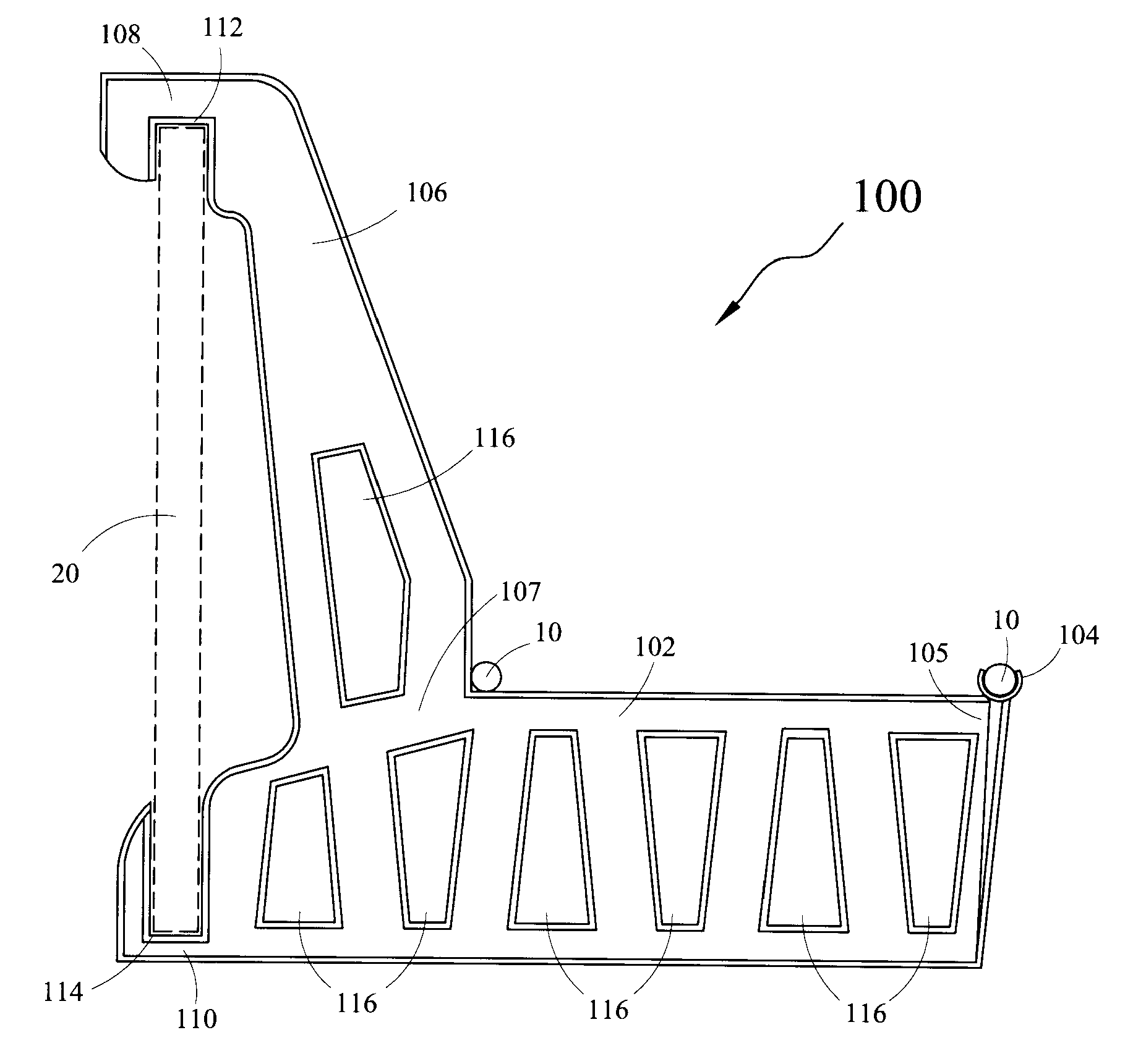
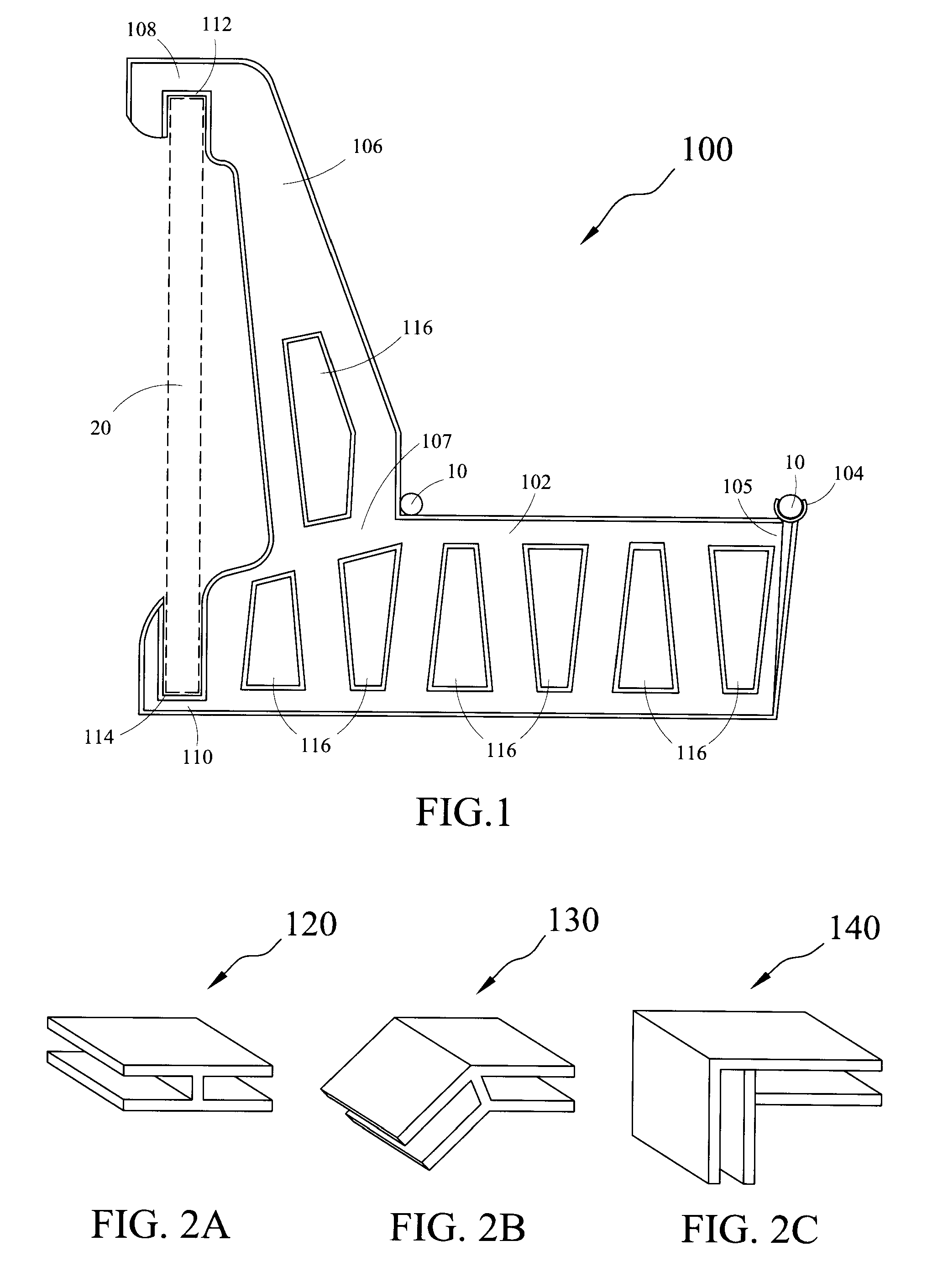
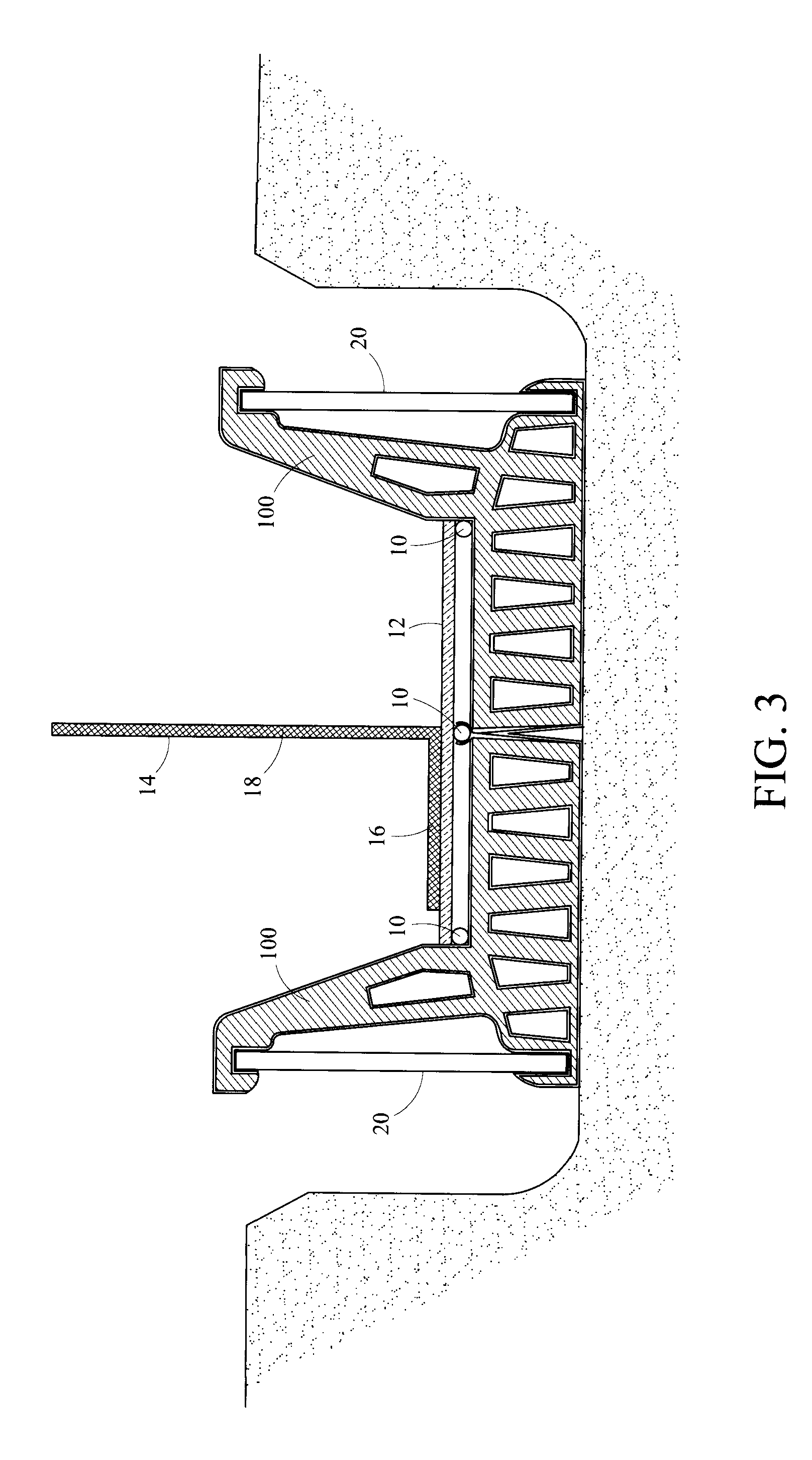
[0011]In yet another aspect, the present invention provides a method for casting a stem wall foundation. The method comprises: snapping a first code spacer onto a first reinforcement bar; snapping a second code spacer onto the first reinforcement bar, the second code spacer snapping on in the opposite direction to the first code spacer, thus delineating the position of the sides of the formwork, the first code spacer and the second code spacer, having a body, a partially encircling clasp protruding from a first end portion of the body, and an elongated neck structure at a second end portion of the body, the elongated neck structure having a top end portion with a top receiving channel, and a bottom end portion with a bottom receiving channel, such that the elongated neck structure of the first code spacer, and the elongated neck structure of the second code spacer facing opposite to each other, and the first reinforcement bar runs through the partially encircling clasp of the first code spacer and the second code spacer, laterally and perpendicularly; disposing a second reinforcement bar at a junction of the elongated neck structure and the body of the first code spacer, laterally and perpendicularly; disposing a third reinforcement bar at a junction of the elongated neck structure and the body of the second code spacer, laterally and perpendicularly; tying the first reinforcement bar, the second reinforcement bar, and the third reinforcement bar using a reinforcement tie, as normally constructed in a stem wall foundation; snapping a first form between the top receiving channel and the bottom receiving channel of the first code spacer; snapping a second form between the top receiving channel and the bottom receiving channel of the second code spacer. Then completing the structural requirements as normal by disposing a vertical reinforcement bar on the reinforcement tie, such that, a neck portion of the vertical reinforcement bar positioned horizontally midway along a length of the reinforcement tie, and a body portion of the reinforcement tie extending vertically and perpendicularly to the neck portion; and pouring liquid concrete between the forms, and allowing the liquid concrete to harden.

Problems solved by technology

Constructing a building in areas / locations prone to natural calamities such as high winds, earthquakes, hurricanes, and floods, presents special challenges.
However, the conventional means of construction does not provide means for carrying a plurality of reinforcing materials, such as, rebars while maintaining essential clearances between the rebar and earth or formwork yet enabling easy flow of concrete throughout the structure during construction.
Most of such blocks in the prior art have been very expensive to produce.
Moreover, it is difficult to maintain the required minimum concrete coverage to the reinforcement.

Method used


Image

  • Building construction system for stem wall foundations
  • Building construction system for stem wall foundations
  • Building construction system for stem wall foundations

Examples


Embodiment Construction

[0021]The exemplary embodiments described herein detail for illustrative purposes are subject to many variations in structure and design. It should be emphasized, however, that the present invention is not limited to a particular building construction system for stem wall foundation, as shown and described. Rather, the principles of the present invention may be used with a variety of configurations and structural arrangements, e.g., for aesthetics, structural purposes, and / or for simplicity in assembling and disassembling. It is understood that various omissions, substitutions of equivalents are contemplated as circumstances may suggest or render expedient, but is intended to cover the application or implementation without departing from the spirit or scope of the claims of the present invention.

[0022]Furthermore, it is to be understood that the phraseology and terminology used herein is for the purpose of description and should not be regarded as limiting. The use of “including,”“c...


PUM


Abstract

A building construction system for setting up and casting a stem wall foundation. The system comprises a plurality of forms, a plurality of code clips configured to fix the forms; and a plurality of code spacers having a body, a partially encircling clasp protruding from a first end portion of the body, and an elongated neck structure at a second end portion of the body and having a top receiving channel and a bottom receiving channel snapping the form in a vertical position. One of the code spacers is snapped onto a reinforcement bar and another of the spacers is distanced adjacently such that the elongated neck structure of code spacers facing opposite to each other, and the reinforcement bar is accommodated on the clasps of both the code spacers laterally and perpendicularly and two reinforcement bars accommodated at a junction of the body and the elongated neck structures.

Description

FIELD OF THE INVENTION[0001]The present invention relates generally to building construction systems, and more particularly, to non-structural spacers having specialized contours for constructing structures, such as, stem wall foundations, and the like, according to building code requirements even in areas prone to natural calamities, in a fast, easy, reliable, inexpensive, and effective manner.BACKGROUND OF THE INVENTION[0002]Constructing a building in areas / locations prone to natural calamities such as high winds, earthquakes, hurricanes, and floods, presents special challenges. The climate and weather conditions in these areas are suited to concrete construction. To facilitate quick and easy construction in these areas, concrete is cast in place over steel reinforcement and in this regard, various types of structural spacers are suggested in the prior art. However, the conventional means of construction does not provide means for carrying a plurality of reinforcing materials, suc...

Claims


Application Information

Patent Timeline
IPC IPC(8): E04B1/41E04B1/38E04G17/06E04C5/16
CPCE02D27/02
Inventor EBANKS, DESMOND A.
Owner EBANKS DESMOND A
Learn More