Method and apparatus for encapsulating wire, hose, and tube splices, connections, and repairs

a technology for encapsulating splices and hoses, applied in the field of encapsulation of splices, connections, and repairs of wires, hoses and tubes, can solve the problems of affecting the appearance of finished results, often failing electrical wiring splices, and significantly more expensive than applying the materials as described

Inactive Publication Date: 2009-10-22
CHARETTE STEVEN MICHAEL
View PDF1 Cites 14 Cited by
  • Summary
  • Abstract
  • Description
  • Claims
  • Application Information

AI Technical Summary

Problems solved by technology

Electrical wiring splices often fail due to corrosion as a result of exposure of the metal portions of the splice to contaminants.
While this method can provide a weathertight seal in the adhesive lined version, the heat applied can easily damage surrounding materials and potentially cause fire, even if the specialized heat gun is used.
In addition, the finished result is often unsightly due to inconsistent application of heat, shape of the splice being sealed (in the event of a soldered joint) or burning.
U.S. Pat. No. 4,151,364 to Ellis discloses a splice with an integral heat shrink covering, which is more convenient than applying separate heat shrink tube, but is significantly more expensive than applying the materials as described in the paragraph above.
Heat damage and the potential for fire also exist using this method.
While this type of splice does not require the application of heat, they can be messy to use and are much more expensive than aforementioned designs.
The following methods, while probably suitable for larger conductors, are not well suited for smaller applications where simplicity, aesthetics, time, and cost are of the essence.

Method used


Image

  • Method and apparatus for encapsulating wire, hose, and tube splices, connections, and repairs
  • Method and apparatus for encapsulating wire, hose, and tube splices, connections, and repairs
  • Method and apparatus for encapsulating wire, hose, and tube splices, connections, and repairs

Examples


first embodiment

FIG. 1—First Embodiment

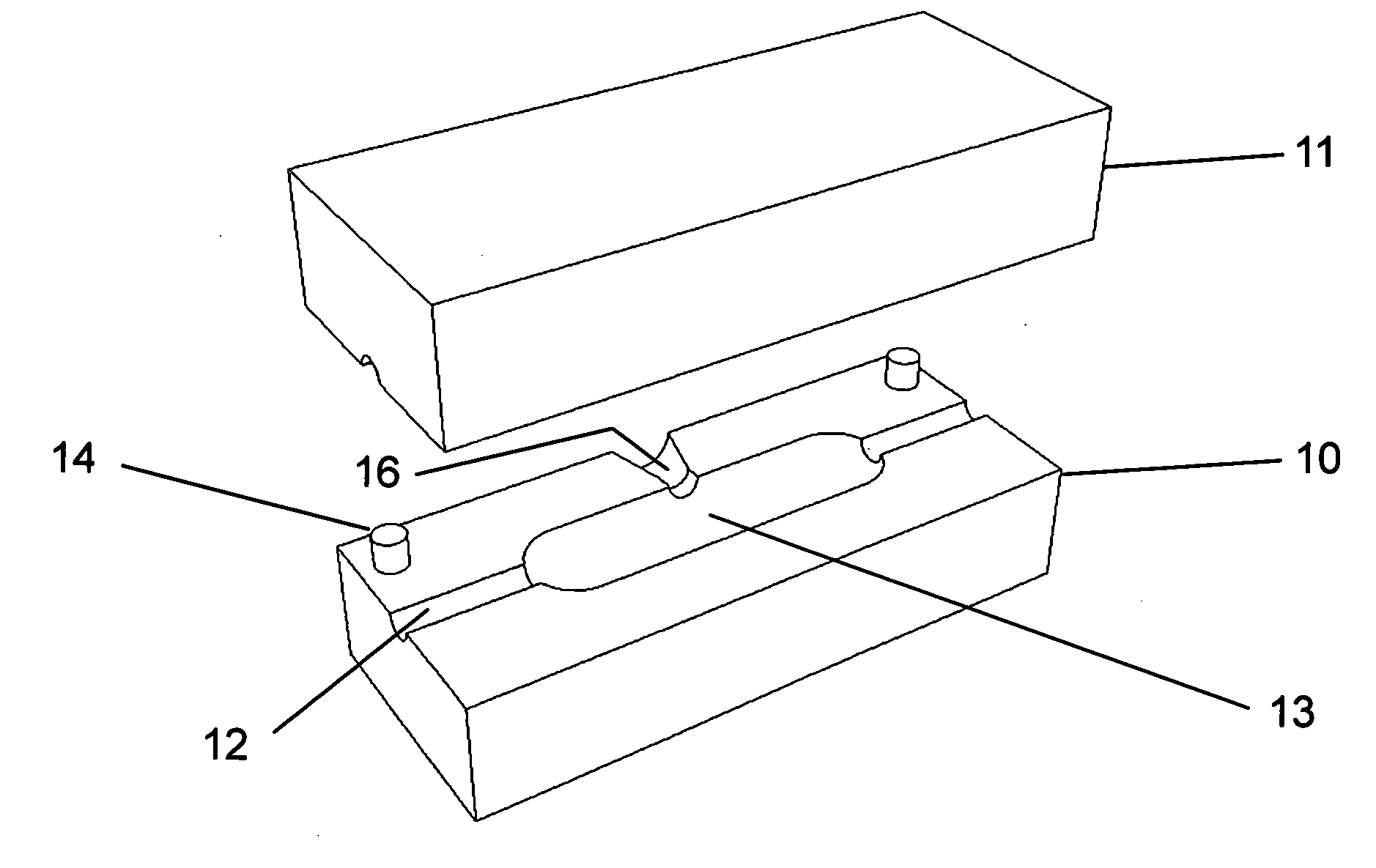
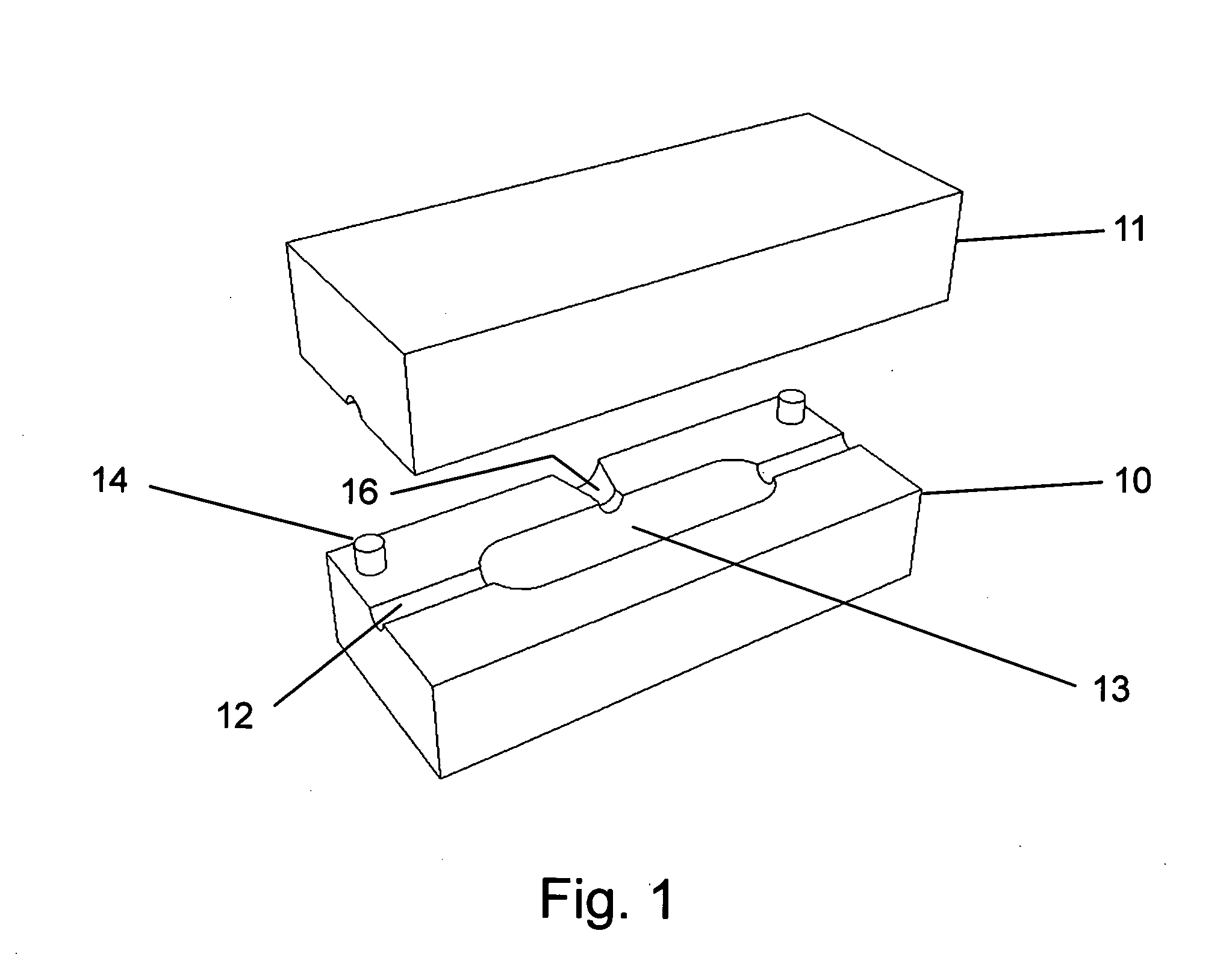
[0032]One embodiment of the invention is illustrated in FIG. 1. The apparatus consists of two mold halves, mold base 10 and mold cover 11. Mold halves are constructed of aluminum or other heat resistant material. The mold halves feature close fitting apertures or grooves 12 allowing a prepared splice assembly 17 being encapsulated passage into the mold cavity 13. The mold halves feature alignment pins 14 for precise alignment of the mold halves, and may or may not have a hinge, latching device, or other alignment aids. The mold cavity 13 is of the appropriate size and shape for the conductor and splice type being encapsulated (i.e. butt splice, crimp cap, terminal, etc.). The mold assembly can have one or more apertures, grooves or openings at each end, one or more openings on adjacent sides, or no openings on one or more sides for conductors so oriented. FIG. 1 shows a perspective view of this embodiment containing the mold base 10 shown with alignment pins 1...


PUM

PropertyMeasurementUnit
sizeaaaaaaaaaa
shapeaaaaaaaaaa
corrosionaaaaaaaaaa

Abstract

An improved method and apparatus for encapsulation of splices, connections, and repairs of wires, tubes, hoses, and similar conductors. Encapsulation is accomplished by securing the area to be encapsulated in a mold set and injecting a hot-melt sealant. Further embodiments allow for the addition of mounting lugs or tabs to the encapsulation for the purpose of mounting or identification. Method can also be used to mold mounting lugs or identification tabs over uninterrupted portions of the aforementioned conductors. The method provides superior resistance to ingress of contaminants and provides strain relief of encapsulated areas by supporting the conductors to reduce movement. The adhesive nature of the sealant reduces the likelihood of conductors being pulled apart.

Description

CROSS-REFERENCE TO RELATED APPLICATIONS[0001]This application claims the benefit of provisional patent application Ser. No. 61 / 044,982, EFS ID 3153640 filed 2008, Apr. 15 by the present inventor.FEDERALLY SPONSORED RESEARCH [0002]Not ApplicableSEQUENCE LISTING OR PROGRAM [0003]Not ApplicableBACKGROUND[0004]1. Field[0005]This application relates to encapsulation of splices, connections, and repairs of wire, hose and tube.[0006]2. Prior Art[0007]Electrical wiring splices often fail due to corrosion as a result of exposure of the metal portions of the splice to contaminants.[0008]Several types of sealing methods have been patented for the encapsulation of these types of splices. U.S. Pat. No. 4,634,615 to Versteegh depicts a heat shrinkable tubing that can be placed over a splice in its expanded state, then be shrunk tight to the splice using heat. A further development of the heat shrink material is defined in U.S. Pat. No. 4,915,139 to Landry, where the tubing lined with an adhesive ...

Claims


Application Information

Patent Timeline
Patent Type & Authority Applications(United States)
IPC IPC(8): H02G1/14B29C45/14
CPCB29C45/14065H02G1/16H02G1/145
Inventor CHARETTE, STEVEN MICHAEL
Owner CHARETTE STEVEN MICHAEL
Why Eureka
Try Eureka