Valve actuator and throttle valve assembly employing the same

a valve actuator and valve assembly technology, applied in the field of valve actuators, can solve the problems that the actuator springs may not be able to provide both the desired spring rate and the desired spring ra

Inactive Publication Date: 2009-10-22
HONEYWELL INT INC
View PDF32 Cites 18 Cited by
  • Summary
  • Abstract
  • Description
  • Claims
  • Application Information

AI Technical Summary

Benefits of technology

[0005]Embodiments of a valve actuator are provided for adjusting the position of a main valve element in relation to the pressure of a fluid supplied by a supply duct. The valve actuator includes a housing, a control pressure valve disposed in the housing, and a piston slidably disposed in the housing and mechanically coupled to the main valve element. The housing has a control pressure chamber therein, which is configured to be fluidly coupled to the supply duct. The control pressure valve is configured to substantially impede fluid flow into the control pressure chamber until the fluid pressure within the supply duct surpasses a minimum actuation pressure. The piston normally resides in a first position and is configured to move toward a second position as the pressure within the control pressure chamber increases.
[0006]In another embodiment, a throttle valve assembly is provided for use in conjunction with a supply duct fluidly coupled to a variable-pressure fluid source. The throttle valve assembly includes a flowbody having a main flow conduit extending therethrough, a valve element disposed within the main flow conduit and movable between an open position and a closed position, and a valve actuator coupled to the flowbody. The valve actuator includes a housing having a control pressure chamber therein, a control pressure valve disposed in the housing, and a piston slidably disposed in the housing and mechanically coupled to the main valve element. The control pressure chamber is configured to be fluidly coupled to the supply duct, and the control pressure valve is configured to substantially impede fluid flow into control pressure chamber until the pressure of the fluid within the supply duct surpasses a minimum actuation pressure. The piston normally resides in a retracted position and is configured to move toward an extended position as the pressure within the control pressure chamber increases.

Problems solved by technology

Unfortunately, in a conventional valve actuator, the actuator spring may not be capable of providing both the desired spring rate and the preload required to achieve a significant minimum actuation pressure.

Method used


Image

  • Valve actuator and throttle valve assembly employing the same
  • Valve actuator and throttle valve assembly employing the same
  • Valve actuator and throttle valve assembly employing the same

Examples


Embodiment Construction

[0011]The following Detailed Description is merely exemplary in nature and is not intended to limit the invention or the application and uses of the invention. Furthermore, there is no intention to be bound by any theory presented in the preceding Background or the following Detailed Description.

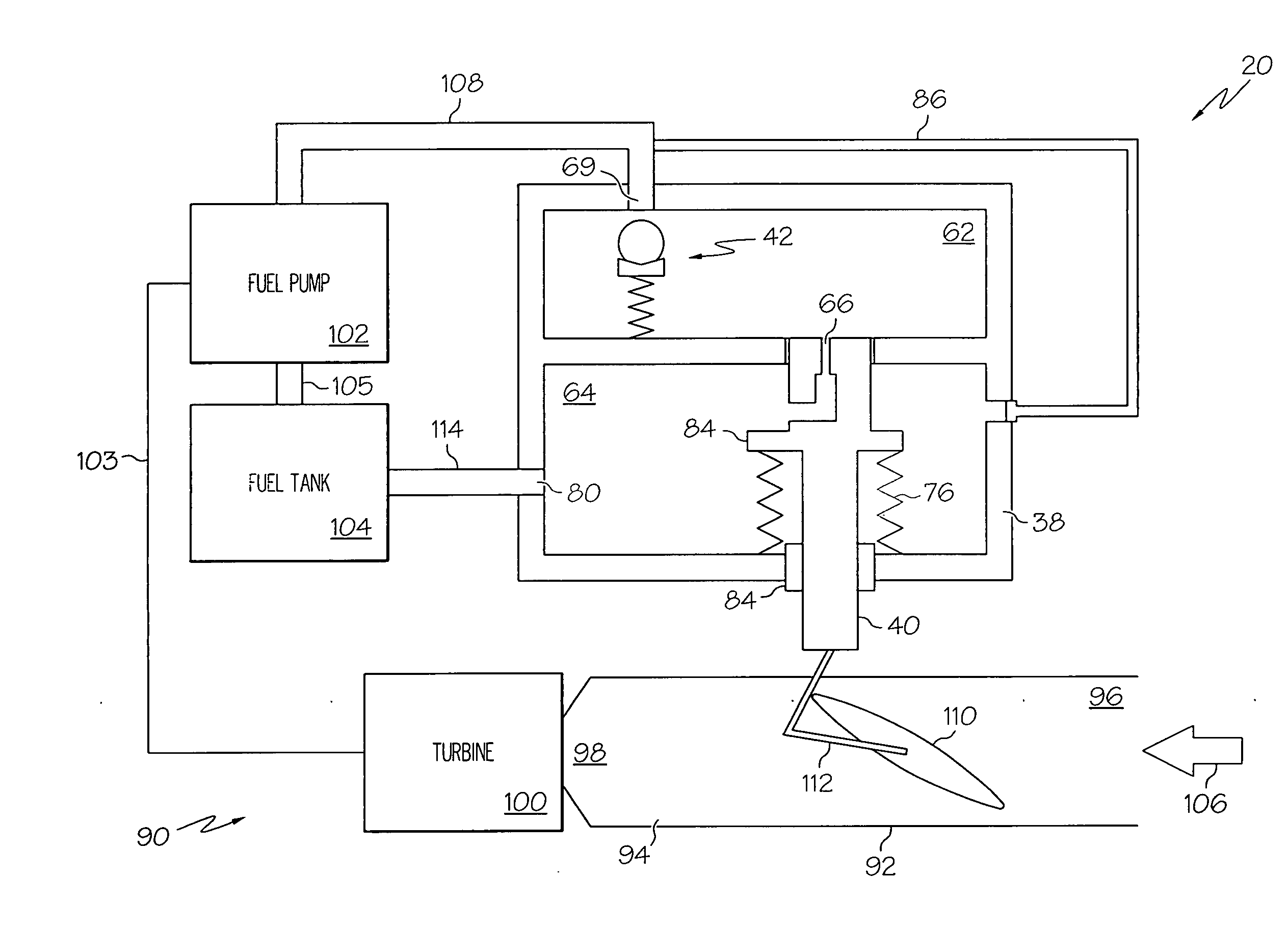
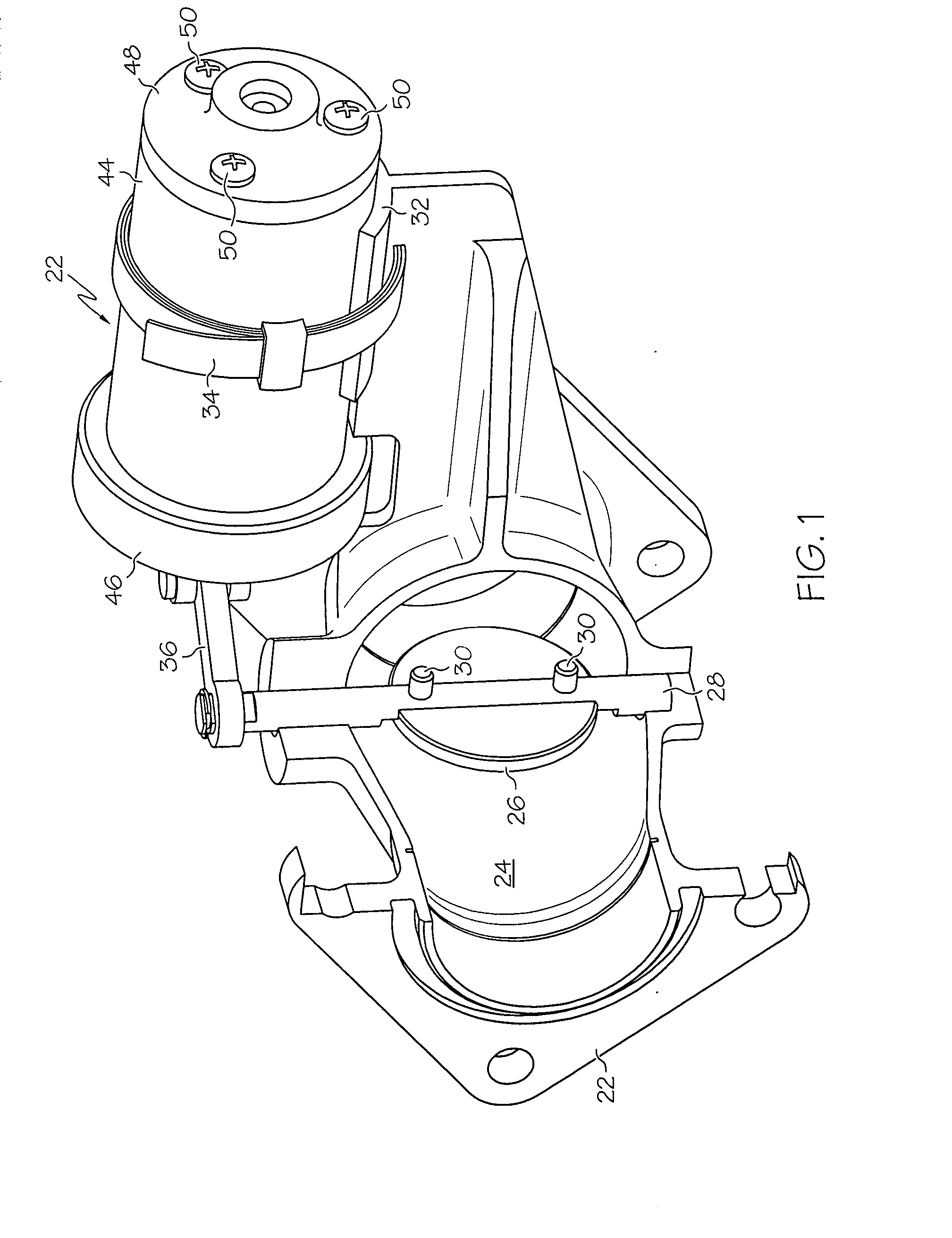
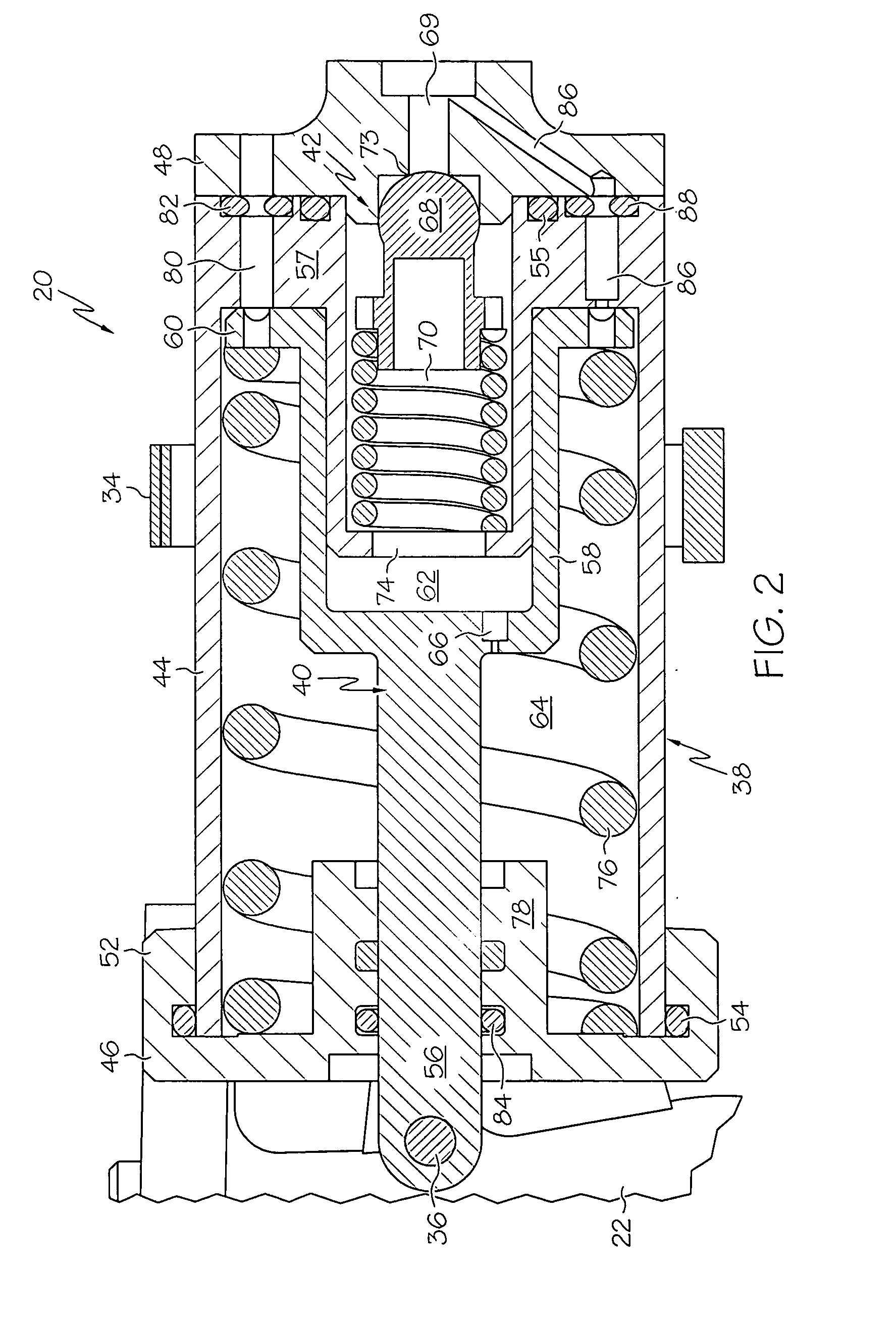
[0012]FIG. 1 is an isometric view of a fluidly-controlled valve actuator 20 in accordance with an exemplary embodiment. Valve actuator 20 is suitable for use in conjunction with a wide variety of hydraulic and pneumatic devices. As a non-limiting example, FIG. 1 illustrates valve actuator 20 in conjunction with a flowbody 22 (partially shown in cutaway) having a main flow conduit 24 extending therethrough. A valve element, in this case a butterfly valve plate 26, is rotatably mounted within main flow conduit 24. More specifically, butterfly valve plate 26 is fixedly coupled to a rotatable shaft 28 by way of first and second fasteners 30. Valve actuator 20 is fixedly mounted to a mounting int...


PUM


Abstract

Embodiments of a valve actuator are provided for adjusting the position of a main valve element in relation to the pressure of a fluid supplied by a supply duct. The valve actuator includes a housing, a control pressure valve disposed in the housing, and a piston slidably disposed in the housing and mechanically coupled to the main valve element. The housing has a control pressure chamber therein, which is configured to be fluidly coupled to the supply duct. The control pressure valve is configured to substantially impede fluid flow into the control pressure chamber until the fluid pressure within the supply duct surpasses a minimum actuation pressure. The piston normally resides in a first position and is configured to move toward a second position as the pressure within the control pressure chamber increases.

Description

TECHNICAL FIELD[0001]The present invention relates generally to a valve actuator and, more particularly, to a fluidly-controlled valve actuator suitable for deployment within, for example, a throttle valve assembly.BACKGROUND[0002]Valve actuators are commonly employed to continually adjust the position of a main valve element (e.g., a butterfly valve plate) disposed within a main flow conduit and thereby control pressurized fluid flow therethrough. A generalized valve actuator may comprise, for example, a piston slidably mounted within a valve housing. A valve linkage mechanically couples the piston to the valve element, and an actuator spring biases the piston toward a retracted position. An actuator chamber is provided in the valve housing and fluidly coupled to a variable-pressure fluid source (e.g., a section of the main flow conduit located downstream of the valve element). As the fluid pressure within the main flow conduit increases, so to does the fluid pressure within the ac...

Claims


Application Information

Patent Timeline
Patent Type & Authority Applications(United States)
IPC IPC(8): F16K31/00
CPCF16K31/1655F16K1/221Y10T137/777
Inventor TANNER, JUSTIN A.BLESSING, LARRYKORTUM, DOUGTANG, BENJAMIN
Owner HONEYWELL INT INC
Why Eureka
Try Eureka