X-ray diffractometer for mechanically correlated movement of the source, detector, and sample position

Active Publication Date: 2009-10-22
BRUKER AXS
View PDF5 Cites 9 Cited by
  • Summary
  • Abstract
  • Description
  • Claims
  • Application Information

AI Technical Summary

Benefits of technology

[0031]In a particularly preferred embodiment of the inventive diffractometer, the detector is designed as a one-dimensional detector with an elongated detector window, wherein the detector window extends in the plane M over its entire length. In the one-dimensional detector, several detector elements are arranged one behind the other on the detector. All detector elements are thereby positioned in the (measuring) plane M. The one-dimensional detector can considerably increase the overall number of simultaneously registered X-ray pulses, which improves the signal-to-noise-ratio. Particular details in connection with the evaluation of measurements with the one-dimensional detector are explained below. The one-dimensional detector is an alternative to the zero-dimensional detector that is used as the simplest case in connection with the invention.
[0032]In another particularly preferred embodiment, the diffractometer is designed in such a fashion that a sample that is disposed

Problems solved by technology

In both cases, the diffractometer constructi

Method used


Image

  • X-ray diffractometer for mechanically correlated movement of the source, detector, and sample position
  • X-ray diffractometer for mechanically correlated movement of the source, detector, and sample position
  • X-ray diffractometer for mechanically correlated movement of the source, detector, and sample position

Examples


Embodiment Construction

[0042]I. Inventive Diffractometers

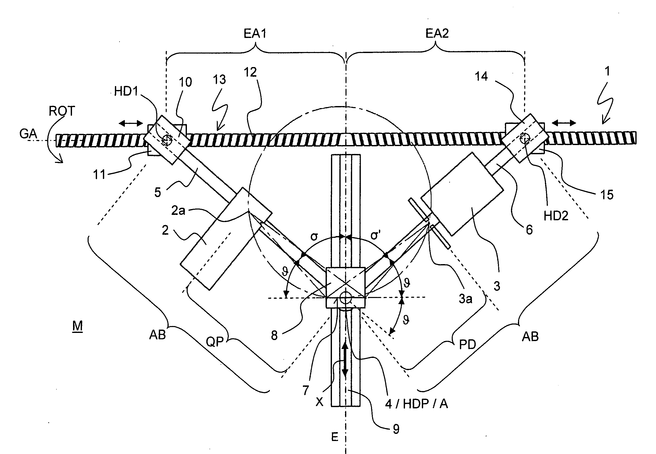
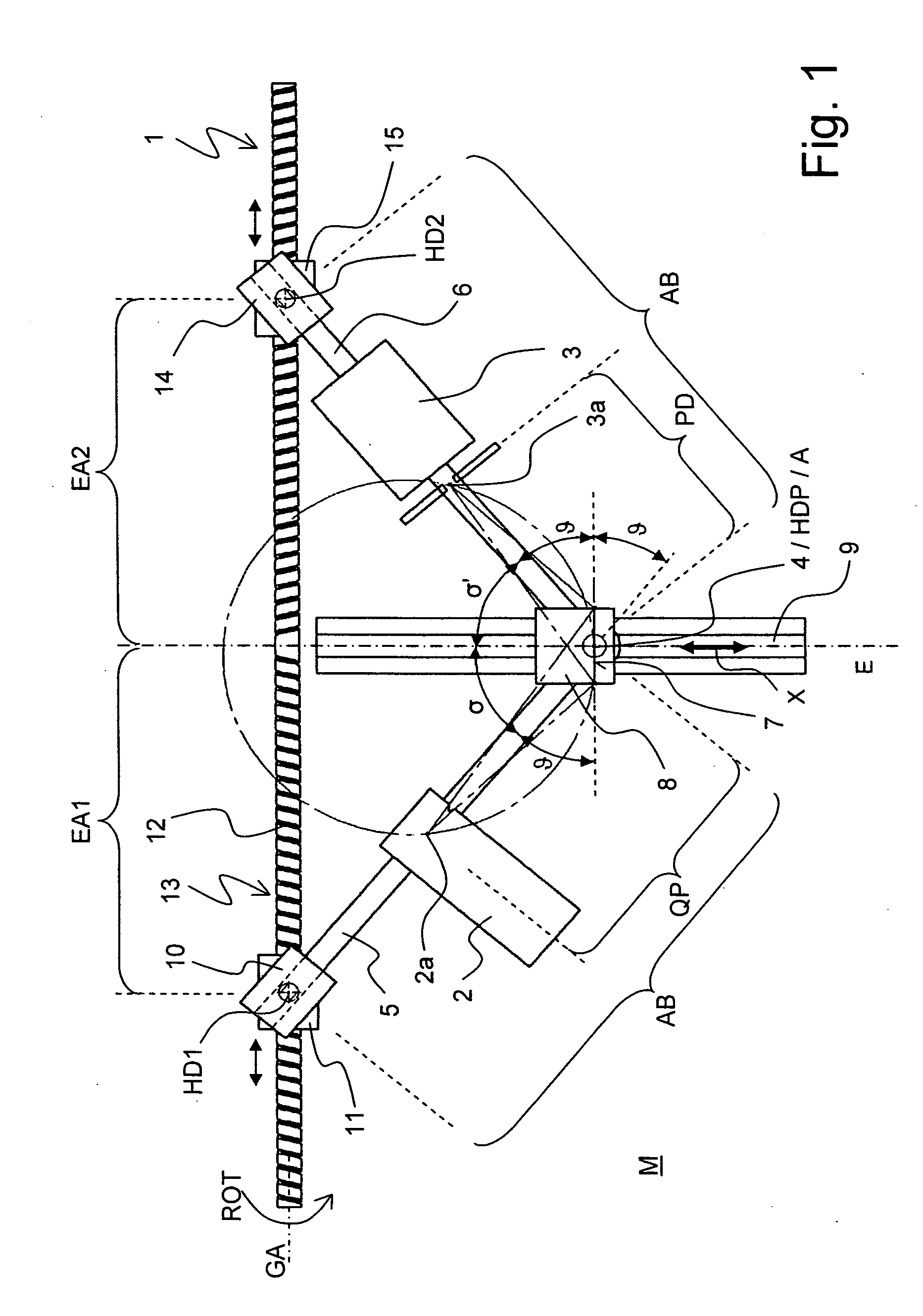
[0043]FIG. 1 shows a first embodiment of an inventive diffractometer 1, comprising a source 2 for X-ray radiation, in the present case an X-ray tube, a detector 3, in the present case a zero-dimensional detector with only one registering element for X-ray radiation, and a sample position 4 for arrangement of a sample (in the present case with a flat sample holder 7; the center of the sample holder 7 is associated with the sample position 4). The sample holder 7 is disposed on a carriage 8 that can freely slide in a vertical stationary rail 9.

[0044]The source 2 is rigidly mounted to a first linkage 5 that is disposed to be rotatable about an axis A (that extends perpendicularly to the plane of the drawing). The axis A thereby extends through the sample position 4. The detector 3 is rigidly mounted to a second linkage 6 that is also disposed to be rotatable about the axis A. The point of intersection of the linkages at the location of the axis A is th...


PUM


Abstract

An X-ray diffractometer (1; 24; 30) has a mechanism without toothed ring and is suited to move the two legs of a goniometer, on which the source (2) and detector (3; 31) are respectively disposed, at the same time and in a correlated fashion, wherein the Θ-angle can be scanned, and at the same time a Θ-Θ-geometry (Bragg-Brentano measurement geometry) is always maintained. This is achieved in that each goniometer leg (or linkage (5, 6; 25, 26)) has a common main center of rotation HDP and also one respective auxiliary center of rotation HD1, HD2. The two auxiliary centers of rotation are symmetrically disposed with respect to a symmetry plane E which contains the main center of rotation, and can be moved on a guidance (13; 13a, 13b) that is symmetrical with respect to the plane E. The main center of rotation can only be moved in the plane E, e.g. along a rail guidance. When the main center of rotation, where the sample to be measured is arranged, is moved in the plane E, the guidance and the goniometer legs cause an opposite angular shift of the goniometer legs, such that the Θ-Θ-geometry with respect to the source and the detector is maintained. The movement of the main center of rotation relative to the guidance can be easily driven by means of one single motor (22).

Description

[0001]This application claims Paris Convention priority of DE 10 2008 020 108.1 filed Apr. 22, 2008 the complete disclosure of which is hereby incorporated by reference.BACKGROUND OF THE INVENTION[0002]The invention concerns a diffractometer, comprising a source for generating X-ray radiation, a sample position for arranging a sample, and a detector for detecting X-ray radiation emitted by the sample, wherein the source and the detector can be rotated with respect to an axis A that extends through the sample position, and wherein the source, the sample position, and the detector are disposed in a common plane M that extends perpendicularly to the axis A.[0003]A diffractometer of this type is disclosed e.g. by the document JP6066741.[0004]X-ray diffractometry is used in a plurality of ways in order to analyze crystalline (and to a certain degree also amorphous) components of samples. X-ray radiation is thereby diffracted on crystal planes in the sample. The spatial intensity distribu...

Claims


Application Information

Patent Timeline
IPC IPC(8): G01N23/20
CPCG01N23/207G01N23/20016
Inventor METTENDORF, KAI UWEBOLZINGER, CLAUSLANGE, JOACHIM
Owner BRUKER AXS
Why Eureka
Try Eureka