Optical receptacle, optical module, and method of manufacturing an optical module

a technology of optical modules and receptacles, applied in the field of optical modules, can solve the problems of deviating condensing points of lenses, affecting the bonging strength of thin filled portions of adhesives, and affecting the quality of optical components, so as to reduce the return light by reflection

Active Publication Date: 2009-10-22
LUMENTUM JAPAN INC
View PDF8 Cites 11 Cited by
  • Summary
  • Abstract
  • Description
  • Claims
  • Application Information

AI Technical Summary

Benefits of technology

[0007]The light receiving element is arranged so as to be deviated from an optical axis of a lens, and the optical receptacle and the optical package such as a CAN packa...

Problems solved by technology

However, in this case, it is necessary to arrange the optical fiber so as to be deviated from the optical axis of the lens, which causes a deviation in spaces to be filled with an adhesive for fixing by bonding the optical receptacle and the optical package to each other.
Then, due to a difference in cure shrinkage caused by a difference in curing time between the adhesive in a thin filled portion and the adhesive in a thick filled portion, a stress is generated in the optical receptacle section, and the optical receptacle section mo...

Method used


Image

  • Optical receptacle, optical module, and method of manufacturing an optical module
  • Optical receptacle, optical module, and method of manufacturing an optical module
  • Optical receptacle, optical module, and method of manufacturing an optical module

Examples


Embodiment Construction

[0031]Hereinafter, an embodiment of the present invention is described in detail with reference to the drawings.

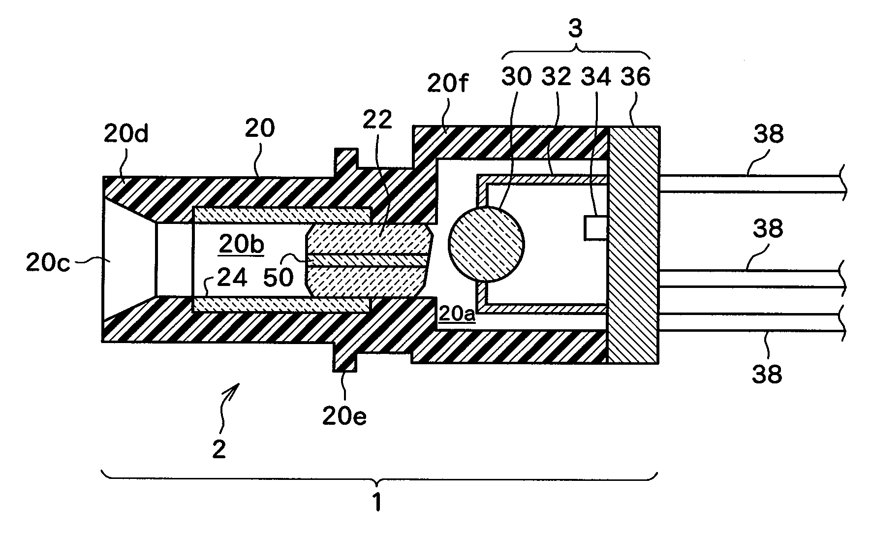
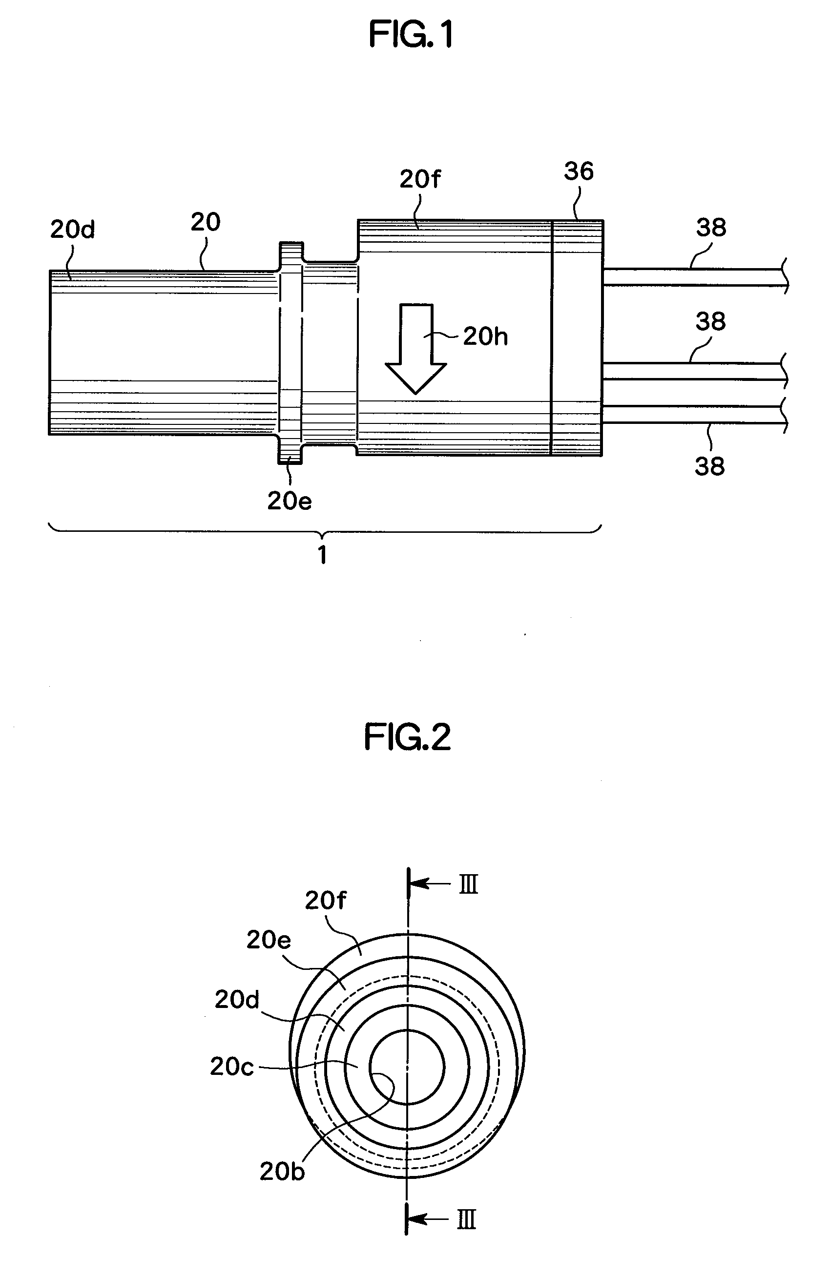
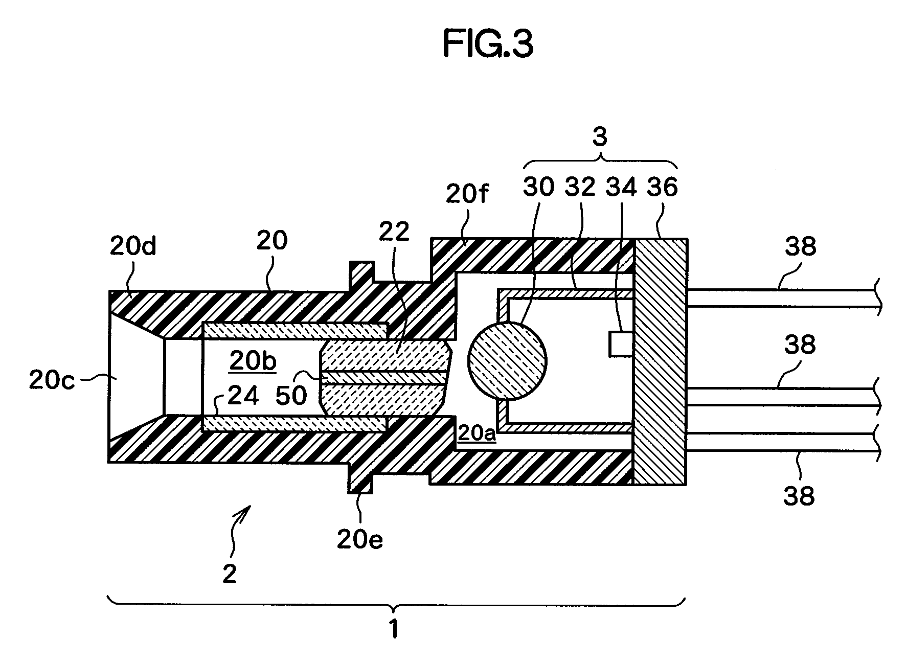
[0032]FIG. 1 is a side view illustrating an optical module 1 according to an embodiment of the present invention. FIG. 2 is a frontal view of the optical module 1 illustrated in FIG. 1. FIG. 3 is a sectional view taken along the line III-III of FIG. 2. FIG. 4 is an assembling drawing of an optical module 1 illustrated in FIGS. 1 to 3.

[0033]As illustrated in FIGS. 1 to 3, the optical module 1 according to this embodiment of the present invention includes an optical receptacle 2 and an optical package 3. Then, the optical receptacle 2 includes an optical receptacle main body 20, a stub 22, and a sleeve 24.

[0034]The optical receptacle main body 20 according to the embodiment of the present invention is constructed by incorporating an integrally formed resin member, and includes an optical package receiving section 20f having a cylindrical outer shape, and an optical fiber ins...


PUM

PropertyMeasurementUnit
Optical propertiesaaaaaaaaaa

Abstract

Provided are an optical receptacle capable of manufacturing an optical module thereby, while suppressing a manufacturing cost, preventing a quality degradation, and suppressing a quantity of returning light by reflection. In the optical receptacle, a recess for receiving a lens and a lens support and a through-hole penetrating from a bottom of the recess toward an exterior are formed, and the recess is formed so that an inner peripheral surface of the recess is fixed to a desired position with respect to an outer peripheral surface of the lens support, in a case where the lens and the lens support are received in the recess such that an optical axis of the lens and an optical axis of the optical fiber to be inserted into the through hole are deviated from each other.

Description

CROSS-REFERENCE TO RELATED APPLICATIONS[0001]The present application claims priority from Japanese application JP 2007-341173 filed on Dec. 28, 2007, the content of which is hereby incorporated by reference into this application.BACKGROUND OF THE INVENTION[0002]1. Field of the Invention[0003]The present invention relates to an optical receptacle, an optical module, and a method of manufacturing an optical module.[0004]2. Description of the Related Art[0005]In recent years, in accordance with a request for achieving a larger capacity and a cost reduction of an optical fiber communication system, a small-sized transmission / reception optical module, for example, a Small Form Factor Pluggable (SFP) module, is being manufactured. As an optical module to be mounted on such a small-sized transmission / reception optical module, there is one called as a CAN package in which a light receiving element and a signal amplifying IC are mounted on a disk-shaped metal plate called as a stem, and in w...

Claims


Application Information

Patent Timeline
IPC IPC(8): G02B6/26G02B6/32B29D11/00
CPCG02B6/4292G02B6/421
Inventor SASADA, MICHIHIDEOKAMURA, YUKITOSHIYAMAMOTO, HIROSHI
Owner LUMENTUM JAPAN INC
Why Eureka
Try Eureka