Optical receptacle and optical module

a technology of optical modules and optical receptacles, applied in the field of optical receptacles and optical modules, can solve the problems of unstable quantity of light emitted from light-emitting elements, and achieve the effect of reducing the return ligh

Active Publication Date: 2022-06-30
ENPLAS CORP
View PDF4 Cites 0 Cited by
  • Summary
  • Abstract
  • Description
  • Claims
  • Application Information

AI Technical Summary

Benefits of technology

[0011]According to the present invention, an optical receptacle and an optical module that can reduce return light without tilting the light-emitting element can be provided.

Problems solved by technology

When light enters the light-emitting element in this manner, the quantity of the light emitted from the light-emitting element becomes unstable.

Method used


Image

  • Optical receptacle and optical module
  • Optical receptacle and optical module
  • Optical receptacle and optical module

Examples


Embodiment Construction

[0017]An optical receptacle and an optical module according to an embodiment of the present invention are elaborated below with reference to the accompanying drawings.

Configuration of Optical Module

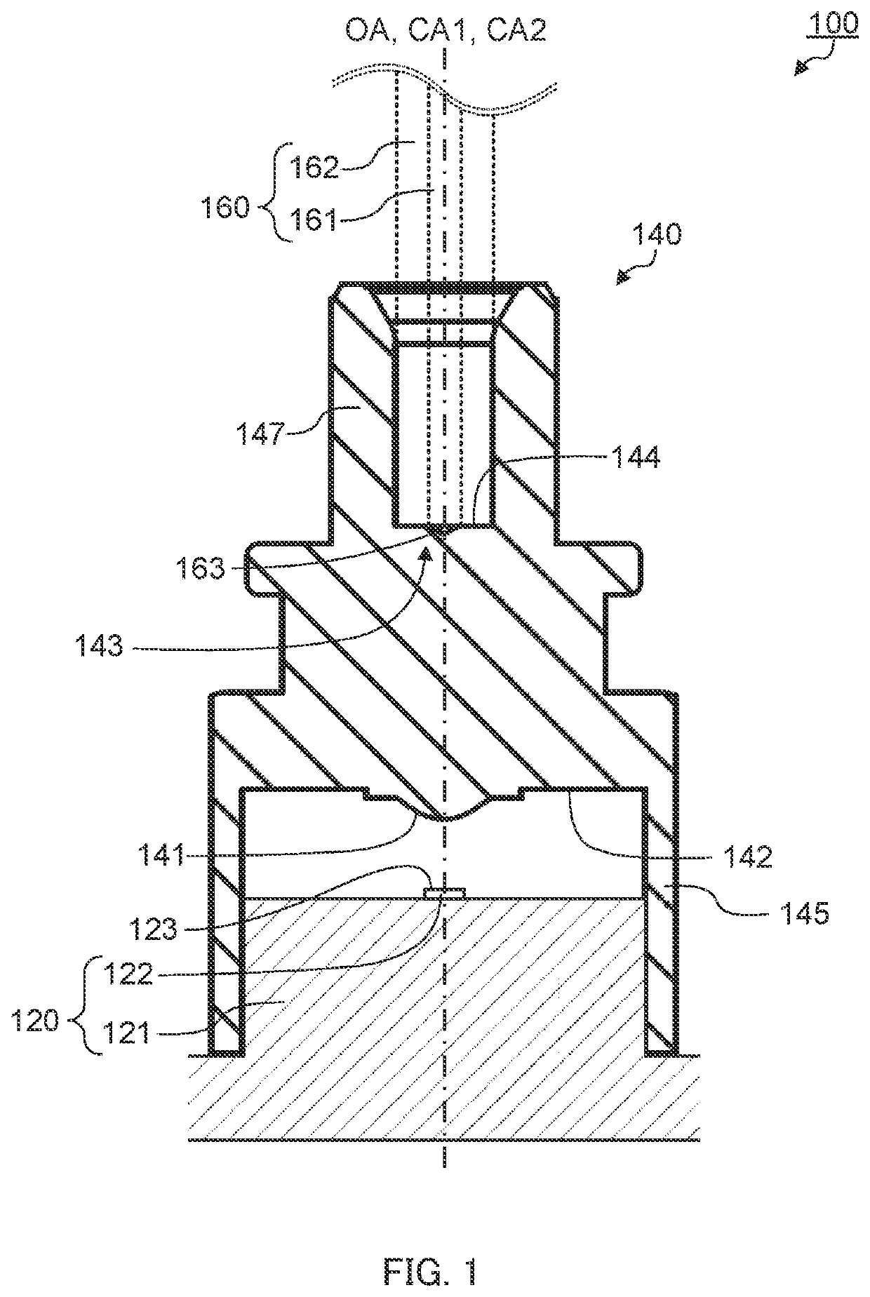
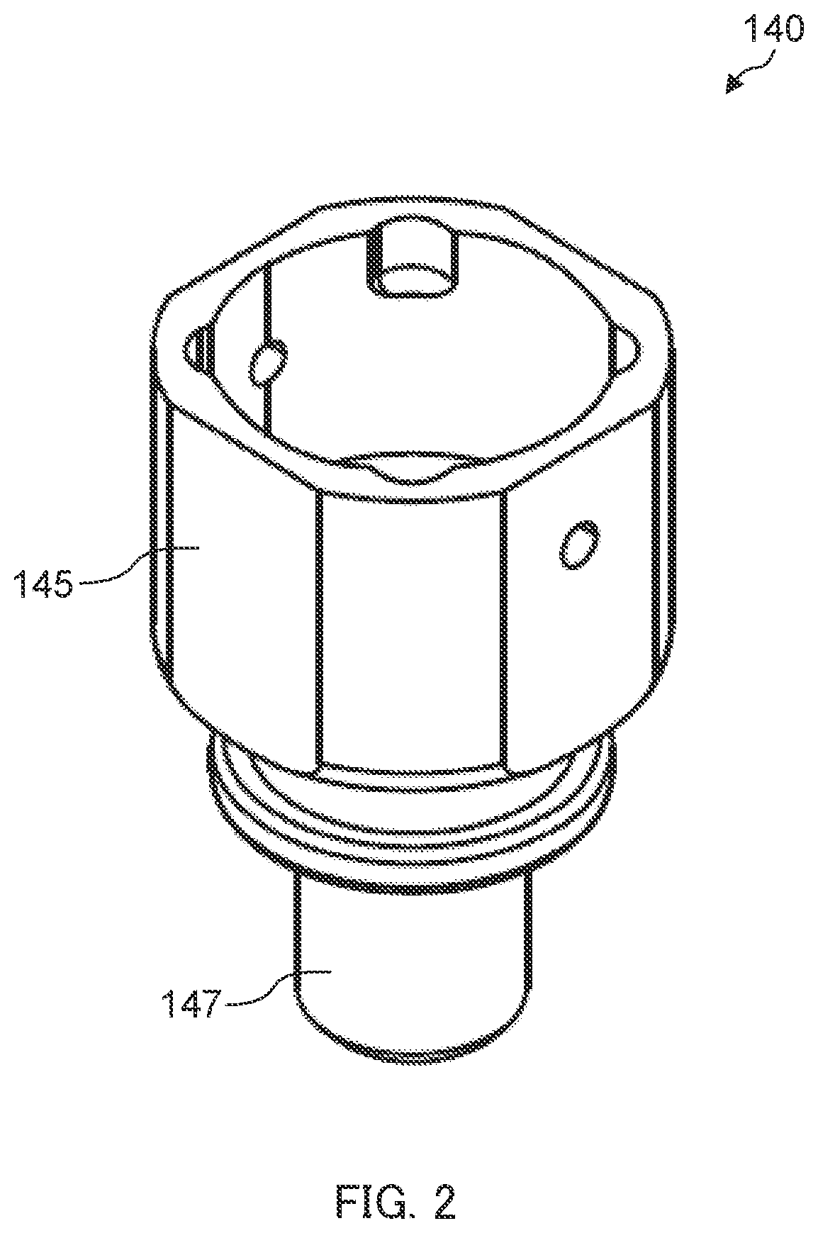
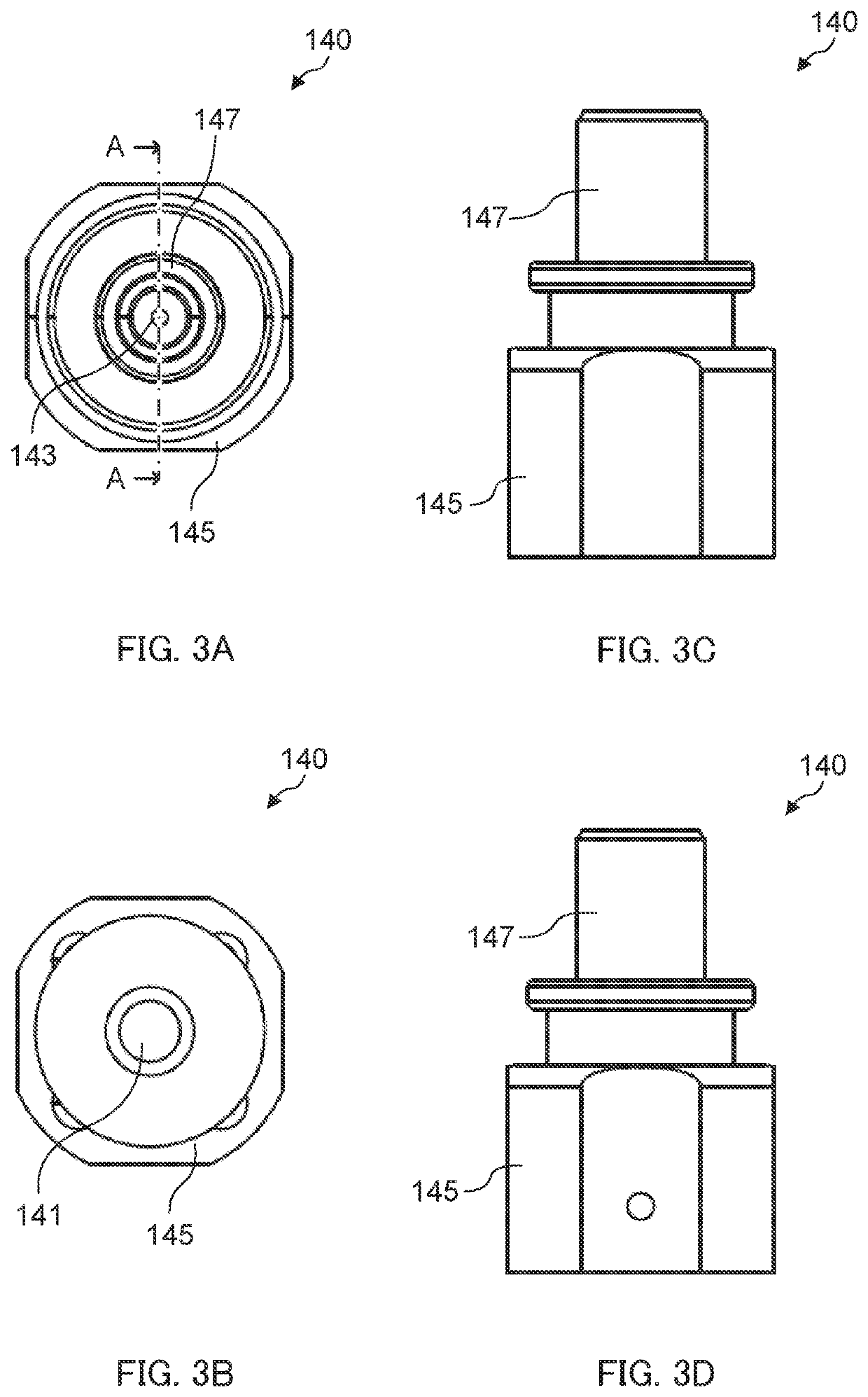
[0018]FIG. 1 is a sectional view of optical module 100 according to Embodiment 1 of the present invention.

[0019]As illustrated in FIG. 1, optical module 100 includes substrate-mounted photoelectric conversion device 120 including light-emitting element 122, and optical receptacle 140. Optical module 100 is a transmitting optical module, and is used with optical transmission member 160 coupled (hereinafter also referred to as “connected”) with optical receptacle 140.

[0020]Photoelectric conversion device 120 includes substrate 121 and light-emitting element 122.

[0021]Substrate 121 supports light-emitting element 122 and is fixed with respect to optical receptacle 140. Substrate 121 is, for example, a glass composite substrate, a glass epoxy substrate, a flexible substrate or the like. Light...


PUM

PropertyMeasurementUnit
angleaaaaaaaaaa
curvature radiusaaaaaaaaaa

Abstract

An optical receptacle is disposed between a light-emitting element and an optical transmission member and configured to optically couple the light-emitting element and the optical transmission member, the optical receptacle including an incidence surface configured to allow incidence of light emitted from the light-emitting element; and an emission surface configured to emit, toward the optical transmission member, light entered from the incidence surface and travelled inside the optical receptacle, the emission surface being an inner surface of a recess. The emission surface includes a first emission surface having a substantially spherical cap shape, and a second emission surface contiguous with the first emission surface, the second emission surface having a shape of a side surface of a substantially frustum shape.

Description

TECHNICAL FIELD[0001]The present invention relates to an optical receptacle and an optical module.BACKGROUND ART[0002]In the related art, in optical communications using an optical transmission member such as an optical fiber and an optical waveguide, an optical module including a light-emitting element such as a surface-emitting laser (for example, vertical cavity surface emitting laser (VCSEL)) is used. The optical module includes one or more photoelectric conversion elements (light-emitting elements or light-receiving elements), and a transmitting optical receptacle, a receiving optical receptacle, or a transmitting and receiving optical receptacle (see, for example, PTL 1).[0003]PTL 1 discloses a receiving module. The optical receptacle disclosed in PTL 1 includes an optical fiber attaching portion, a photoelectric conversion device attaching portion, and a lens. A light-receiving element is disposed opposite to the photoelectric conversion device attaching portion, and an optic...

Claims


Application Information

Patent Timeline
Patent Type & Authority Applications(United States)
IPC IPC(8): G02B6/42
CPCG02B6/4206G02B6/4292G02B6/4204G02B6/4263
Inventor KANI, HIROYOSHISATO, HONOKA
Owner ENPLAS CORP
Why Eureka
Try Eureka