Optical device and movable reflector

A technology of optical parts and light reflection, applied in optical components, optics, light guides, etc., can solve problems such as signal light waveform distortion, communication errors, etc.

Inactive Publication Date: 2010-05-05
SUMITOMO ELECTRIC IND LTD
View PDF7 Cites 0 Cited by
  • Summary
  • Abstract
  • Description
  • Claims
  • Application Information

AI Technical Summary

Problems solved by technology

Such returning light distorts the waveform of the signal light propagating in the optical waveguides 11 and 12, causing communication errors.

Method used


Image

  • Optical device and movable reflector
  • Optical device and movable reflector
  • Optical device and movable reflector

Examples


Embodiment approach 1

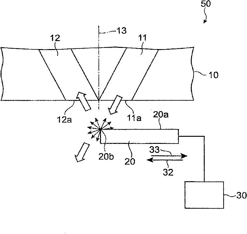
[0054] Figure 4 It is a schematic plan view showing the optical component of Embodiment 1. The optical component is a variable optical attenuator 100 . The variable optical attenuator 100 has a planer lightwave circuit (Planer Lightwave Circuit: PLC) 10 , a movable mirror 21 , and a mirror driving device 30 . The mirror 21 and the mirror driving device 30 constitute a movable reflecting device 91 . These components are housed in a housing (not shown).

[0055] PLC10 has two optical waveguides 11 and 12. The optical waveguides 11 and 12 are along Figure 4 A planar waveguide that extends parallel to the paper surface. The optical waveguides 11 and 12 are made of quartz glass, for example. The optical waveguides 11 and 12 are such as Figure 4 As shown, the reference plane 13 perpendicular to the paper surface has symmetrical (in this embodiment, mirror symmetrical) end portions. These end portions extend linearly with an inclination of an angle α with respect to the refere...

Embodiment approach 2

[0068] Figure 8 It is a schematic plan view showing the variable optical attenuator 200 of the second embodiment. The variable optical attenuator 200 includes a PLC 60 instead of the PLC 10 in the variable optical attenuator 100 of the first embodiment. Another configuration of the variable optical attenuator 100 is the same as that of the first embodiment.

[0069] The PLC 60 has three optical waveguides 61 , 62 and 63 . These optical waveguides are compatible with Figure 8 A planar waveguide that extends parallel to the surface of the paper is made of, for example, quartz glass. The optical waveguides 61 and 62 have an optical axis 68 including the optical waveguide 63, and are relatively Figure 8 The reference plane perpendicular to the plane of the paper is arranged as symmetrical (mirror symmetrical in this embodiment) ends. These end portions each extend in a straight line with an inclination of an angle α with respect to the optical axis 68 . These ends therefo...

Embodiment approach 3

[0074] Figure 9 It is a schematic plan view showing the variable optical attenuator 300 of the third embodiment. The variable optical attenuator 300 has a movable mirror 22 instead of the movable mirror 21 in the variable optical attenuator 100 of the first embodiment. The mirror 22 and the mirror driving device 30 constitute a movable reflecting device 92 . Other configurations of the variable optical attenuator 300 are the same as those of the first embodiment.

[0075] The movable mirror 22 is a light reflector having a light reflection surface 22a. Movable mirror 22 is with Figure 9 A columnar body that extends vertically to the plane of the paper and has a section along the same vertical direction as the plane of the paper. The light reflection surface 22a has an extremely high reflectance (for example, 90% or more) with respect to light of a predetermined wavelength propagating through the optical waveguides 11 and 12 . The light reflection surface 22 a faces the ...


PUM


Abstract

An optical device has first and second non-parallel optical paths, and a light reflecting surface movable along the defined path. The reflecting surface may have a first and second planar portion connected to the first planar portion. The first planar portion receives light from the first path to reflect the light toward the second path. The second planar portion may form an angle theta 1 with thefirst planar portion. Angle theta 1 satisfies a condition of 175 DEG <=theta 1<180 DEG in either clockwise or counterclockwise rotation from the first planar portion. Returning light to a first optical path can be reduced in an optical component varying the power of a light traveling from the first optical path to a second optical path.

Description

technical field [0001] The present invention relates to an optical component that changes the power of light propagating from a first optical path to a second optical path, and a movable reflector used in the optical component. Background technique [0002] In optical communication, optical components, such as variable optical attenuators and optical switches, are often used to adjust the power of optical signals propagating in optical waveguides. An example of such an optical component is disclosed in "Micro-Opto-Mechanical 2x2 Switch for SingleMode Fibers based on Plasma-Etched Silicon Mirror and Electrostatic Actuation" (preceding 11th IEEE Workshop on Micro-Electro-Mechanical System, 1998) in addition to C.Marxer , pp. 233-237). In this example, a reflective mirror is arranged in the optical path from the first optical waveguide to the second optical waveguide, and the power of the light incident from the first optical waveguide to the second optical waveguide is adjust...

Claims


Application Information

Patent Timeline
Patent Type & Authority Patents(China)
IPC IPC(8): G02B6/00G02B26/02G02B6/12G02B6/26G02B6/34G02B6/35
CPCG02B6/29391G02B6/29311G02B6/266G02B6/352G02B6/3568G02B6/2938G02B6/3514G02B6/3594
Inventor 盐崎学片山诚佐野知已多久岛道子
Owner SUMITOMO ELECTRIC IND LTD
Why Eureka
Try Eureka