Methods and Devices to Clear Obstructions from Medical Tubes

a technology of medical tubes and obstructions, applied in the direction of suction drainage containers, applications, catheters, etc., can solve the problems of obstructing the suction pathway within the tube, rendering the medical tube partially or totally non-functional, and causing serious or potentially life-threatening consequences

Active Publication Date: 2009-10-22
CLEAR CATHETER SYSTEMS
View PDF83 Cites 85 Cited by
  • Summary
  • Abstract
  • Description
  • Claims
  • Application Information

AI Technical Summary

Problems solved by technology

Unfortunately, however, bodily secretions (particularly those including blood or blood platelets) often form clots within medical tubes, which can partially or totally obstruct the suction pathway within the tube.
Obstruction of a medical tube can impact its effectiveness to remove the fluid and other material for which it was originally placed, eventually rendering the medical tube partially or totally non-functional.
In some cases, a non-functional tube can have serious or potentially life-threatening consequences.
For example, if there is a blockage in a chest tube following cardiac or pulmonary surgery, the resulting accumulation of fluid around the heart and lungs without adequate drainage can cause serious adverse events such as pericardial tamponade and pneumothorax.
In addition to chest tubes used in heart, lung and trauma surgery, other medical tubes are prone to clogging as well, including feeding tubes, surgical wound drains, urinary catheters, cardiovascular catheters and others.
There are few effective techniques to manage medical tube clogging when it occurs.
None of the above techniques is particularly effective.
Moreover, they are time consuming and can be quite painful if the patient is awake and alert when they are performed, due to tugging on the medical tube.
Tugging on chest tubes whose terminal ends have been placed near the pleura or pericardium can be especially painful.
In addition, the ‘stripping’ technique is known to generate short bursts of extreme negative pressure within chest tubes, which in turn draws a strong suction in the body cavity where its terminal end has been placed.
This can be quite dangerous in certain circumstances.
For example, negative pressures of magnitude greater than −300 cm of water can be generated adjacent suture lines on coronary anastomosis, etc., which can disrupt some of the work that was done during a prior surgery.
As a result, many surgeons have banned stripping their patients' chest tubes due to the potential for complications.
When the above techniques fail to clear a potentially dangerous clot within the tube, a more invasive technique must be used.
But it is highly undesirable for a number of reasons.
First, it compromises the sterile field within the chest tube system by exposing the internal environment within that system to the external environment, potentially introducing bacteria inside the chest.
Breaking the seal on this system causes loss of the normal physiologic negative pressure inside the chest.
This can result in lung collapse (pneumothorax) while suctioning the chest tube.
Additionally, the suction catheter can easily be passed beyond the end of the chest tube, which has the potential to injure the heart or lungs, which could be life threatening.
Finally, this procedure is time consuming and usually can only be performed by physicians due to the associated dangers.
Thus it is only occasionally done in extreme situations when a clogged chest tube is causing a serious acute problem.

Method used


Image

  • Methods and Devices to Clear Obstructions from Medical Tubes
  • Methods and Devices to Clear Obstructions from Medical Tubes
  • Methods and Devices to Clear Obstructions from Medical Tubes

Examples


Embodiment Construction

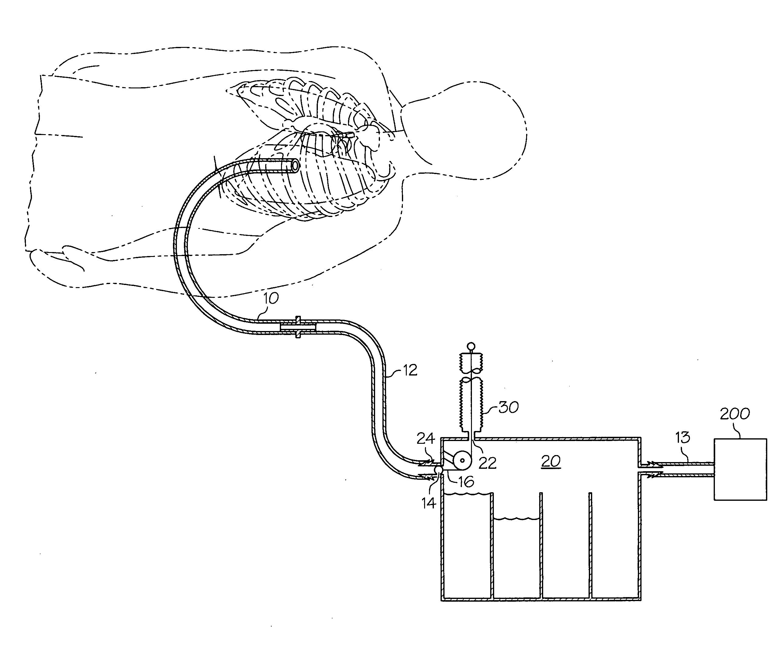
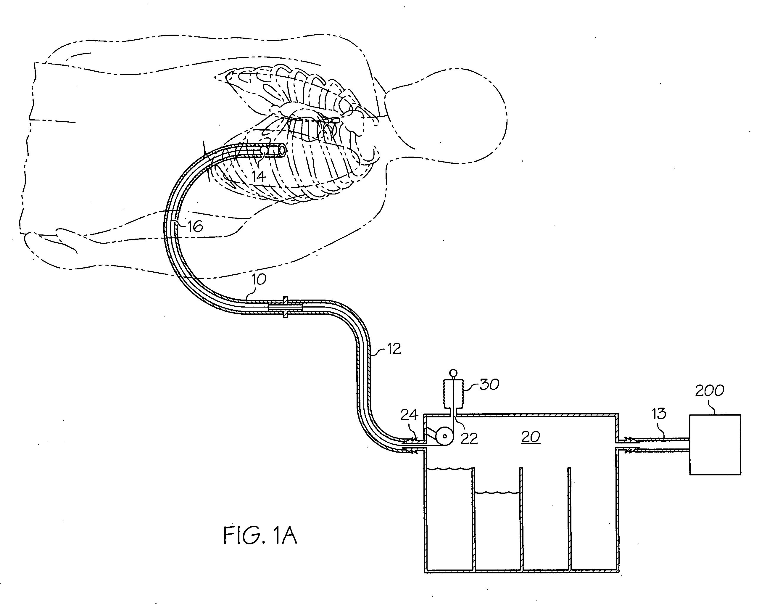
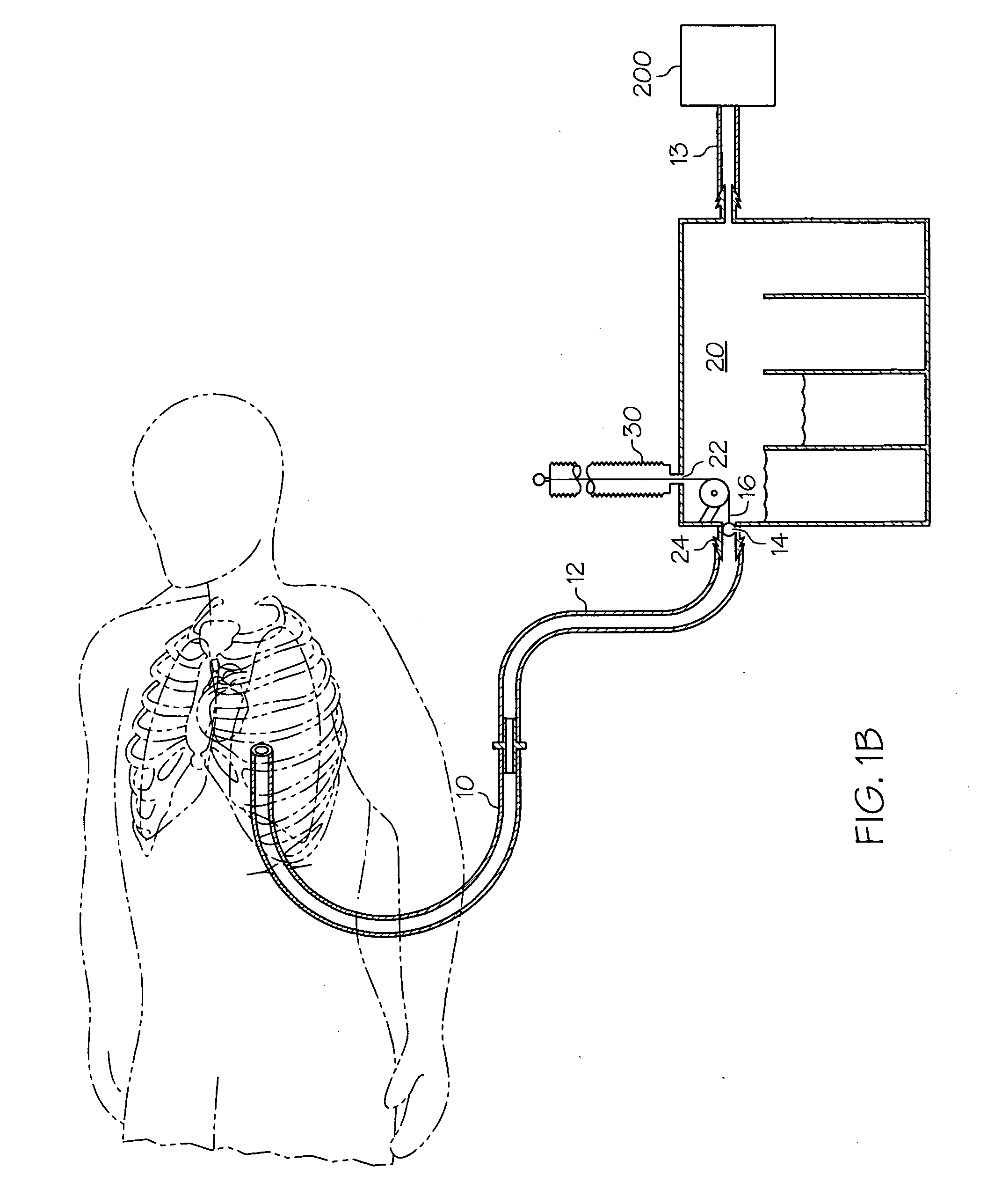
[0024]As used herein, the terms proximal and distal are generally to be construed with reference to a patient that has been or is to be fitted with a medical tube, such as a chest tube. For example, the distal end or region of a medical tube (e.g. chest tube) is that end or region that is to be inserted into or disposed more adjacent (e.g. within) the patient during use, as compared to the opposite end or region of the medical tube (chest tube). Similarly, a distal element (or the distal side or region of an element) is nearer to the patient, or to the distal end of the chest tube, than a proximal element (or the proximal side or region of an element). Also herein, the “terminal” end of a tube, wire or member refers to its distal end.

[0025]FIG. 1 shows a schematic representation of a medical tube being used to drain accumulated fluid from within the body cavity of a patient, in accordance with an exemplary embodiment of the invention. In FIG. 1 the medical tube is inserted into and ...


PUM


Abstract

A device for clearing obstructions from a medical tube, such as a chest tube, is disclosed in various embodiments. In embodiments, the device features a guide wire that extends from a drainage canister and can be advanced and withdrawn through a medical tube, such as a chest tube, via an actuator. The guide wire is actuated so as to maintain the sterile field within the chest tube and the associated suction pathway. Methods of clearing a medical tube of obstructions using such a device are also disclosed.

Description

CROSS-REFERENCE TO RELATED APPLICATIONS[0001]This application is a continuation-in-part of U.S. patent application Ser. No. 12 / 359,826 filed Jan. 26, 2009, which claims the benefit of U.S. provisional patent application Ser. No. 61 / 189,850 filed Aug. 22, 2008, and U.S. provisional patent application Ser. No. 61 / 023,829 filed Jan. 25, 2008. The contents of all the foregoing applications are incorporated herein by reference.BACKGROUND[0002]1. Field of the Invention[0003]The invention relates to methods and devices to clear obstructive debris from medical tubes. More particularly, it relates to such a device having a clearance member that can be actuated to draw such debris proximally in a medical tube without compromising the sterile field.[0004]2. Description of Related Art[0005]Millions of medical tubes are used every year to drain bodily fluids and secretions from within body orifices. For example, such tubes can be used to drain fluid from one's bladder, from the colon or other po...

Claims


Application Information

Patent Timeline
Patent Type & Authority Applications(United States)
IPC IPC(8): A61M1/00A61M5/00
CPCA61B19/34A61B2019/343B08B9/0436A61M2025/0019A61M1/0013A61B90/70A61B2090/701A61M1/61
Inventor BOYLE, JR., EDWARD M.
Owner CLEAR CATHETER SYSTEMS
Why Eureka
Try Eureka