Land vehicle braking system

Inactive Publication Date: 2009-10-22
DESBRUNES HERMAN
View PDF10 Cites 94 Cited by
  • Summary
  • Abstract
  • Description
  • Claims
  • Application Information

AI Technical Summary

Benefits of technology

[0005]It is another object of the invention to provide a braking system of the type described that will automatically stop a land vehicle when following a vehicle with illuminated brake lights or when approaching a school bus with flashing warning lights. Thus, a driver of a vehicle employing the system cannot inadvertentl

Problems solved by technology

If a driver is inattentive or his vehicle is somehow out-o

Method used


Image

  • Land vehicle braking system
  • Land vehicle braking system
  • Land vehicle braking system

Examples


Embodiment Construction

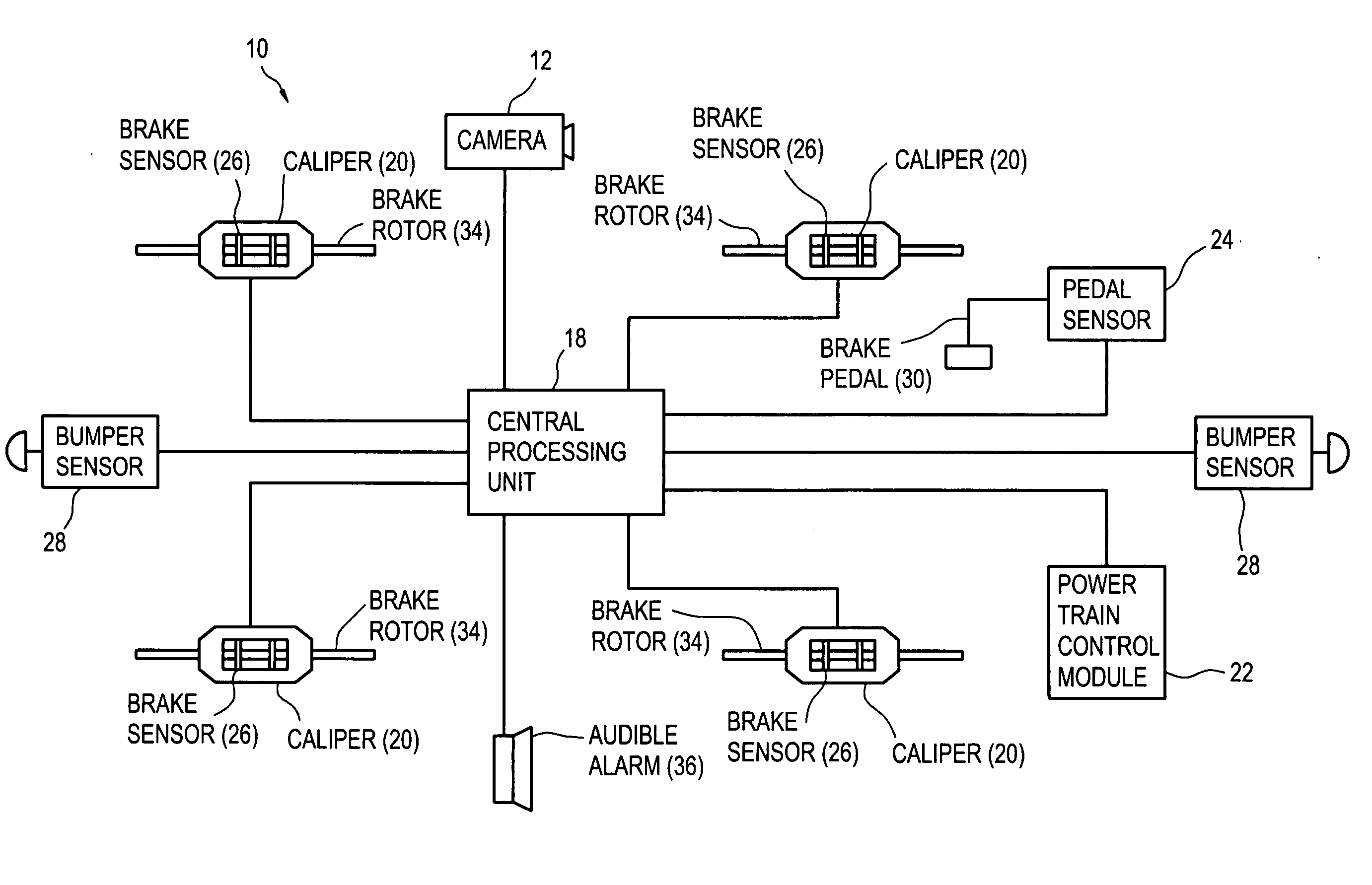
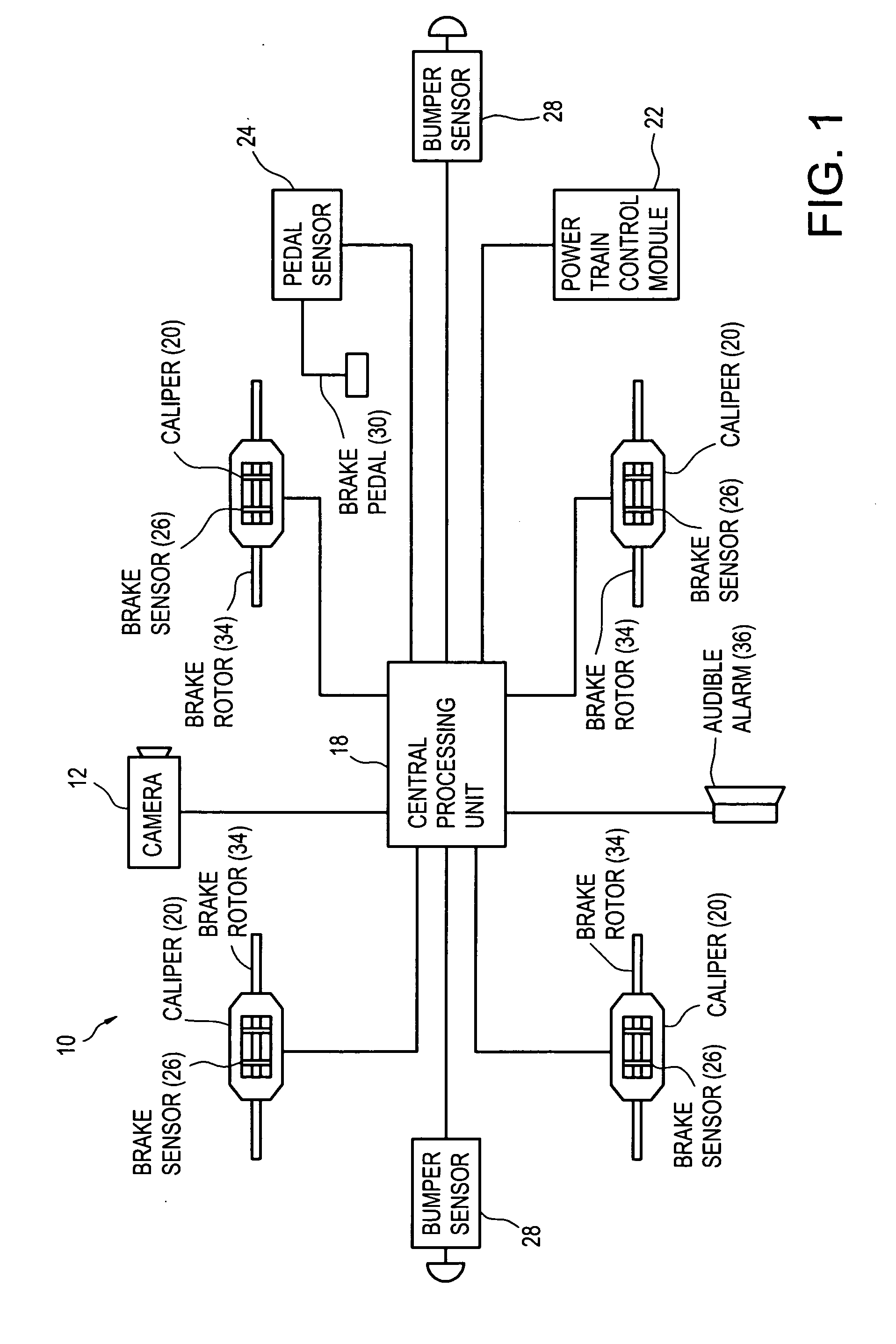
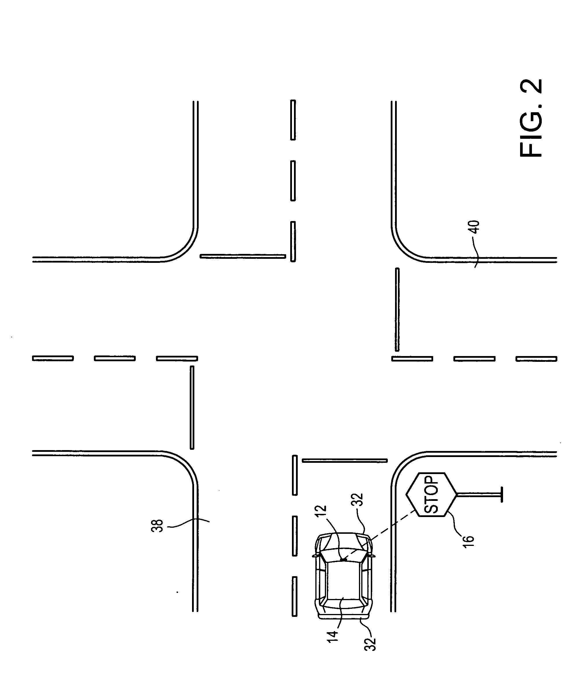
[0012]Referring now to the FIGS., a land vehicle braking system in accordance with the present invention is shown at 10. System 10 includes a video camera 12 that is mounted on a land vehicle 14 for detecting sources of red light like traffic lights and stop signs as at 16 within its field of view. Camera 12 is connected to a central processing unit (CPU) 18 that serves as a controller of a number of brake calipers 20 and a power train control module 22 of vehicle 14. A number of sensors 24, 26 and 28 being connected respectively to the brake pedal 30, brake calipers 20, and bumpers 32 of vehicle 14 transmit data signals to CPU 18 that are considered by CPU 18 in controlling calipers 20 and power train control module 22.

[0013]Vehicle 14 is normally stopped by the application of downward pressure to brake pedal 30. Pedal 30 is located at the front of vehicle 14 where it can be easily pressed by one foot of the vehicle driver. A pedal sensor 24 connected to pedal 30 detects the amount...


PUM


Abstract

A braking system in a land vehicle having wheels for movement and a motor rotating the wheels. The braking system includes a brake rotor that is secured to one of the wheels. A brake caliper is secured to the vehicle for grasping the rotor in response to a caliper actuation signal. A brake pedal is secured to the land vehicle for movement by the vehicle driver. A pedal sensor is connected to the pedal for sensing the movement thereof and generating a braking signal in response to the movement of the pedal. A power train control module is secured to the vehicle for controlling the speed at which the motor rotates the wheels in response to a deactivation signal. A camera is mounting on the vehicle for generating a video signal representative of the incident light entering the camera. A central processing unit (CPU) is connected to the pedal sensor, the brake caliper and the camera. The CPU is adapted to receive the braking signal from the pedal sensor and, in response thereto, transmit a caliper actuation signal to the brake caliper. The CPU is also adapted to receive the video signal from the camera and process the video signal to determine whether the incident light entering camera includes light of a red color. In response to detecting light of a red color, CPU transmits a caliper actuation signal to the brake caliper and a deactivation signal to the power train control module.

Description

FIELD OF THE INVENTION[0001]The present invention relates generally to electrical communication apparatus and, more particularly, to land vehicle alarms and indicators of collision or contact with external objects.BACKGROUND OF THE INVENTION[0002]Preventing collisions at roadway intersections has long been a goal of civil engineers working in the field. Numerous design features are commonly incorporated into intersections to minimize the likelihood of collisions. Typical of these features are: well-lit signals, bold signs and roadway markings, reduced speed zones, flat and straight roadway grades, and textured roadway surfaces for enhancing traction. These features all lengthen the effective stopping distance available to a vehicle at an intersection thereby increasing margins of safety.[0003]Driver misbehavior has reduced the effectiveness of safe roadway designs. Inattentiveness, speeding, racing, and drinking have caused drivers cruise past stop signs and red light without notici...

Claims


Application Information

Patent Timeline
IPC IPC(8): G06F19/00B60Q1/00
CPCY10T477/814B60T7/22
Inventor DESBRUNES, HERMAN
Owner DESBRUNES HERMAN
Why Eureka
Try Eureka