

Cooling structure of internal combustion engine
- Summary
- Abstract
- Description
- Claims
- Application Information
AI Technical Summary
Benefits of technology
Problems solved by technology
Method used
Image

Examples
Embodiment Construction
[0028]Embodiments of the invention will be described below with reference to the appended drawings.
[0029]In the below-described embodiment an example will be explained in which the cooling structure of an internal combustion engine in accordance with the invention is applied to a linear four-cylinder internal combustion engine, but the invention may be applied to an internal combustion engine of any system and any number of cylinders.
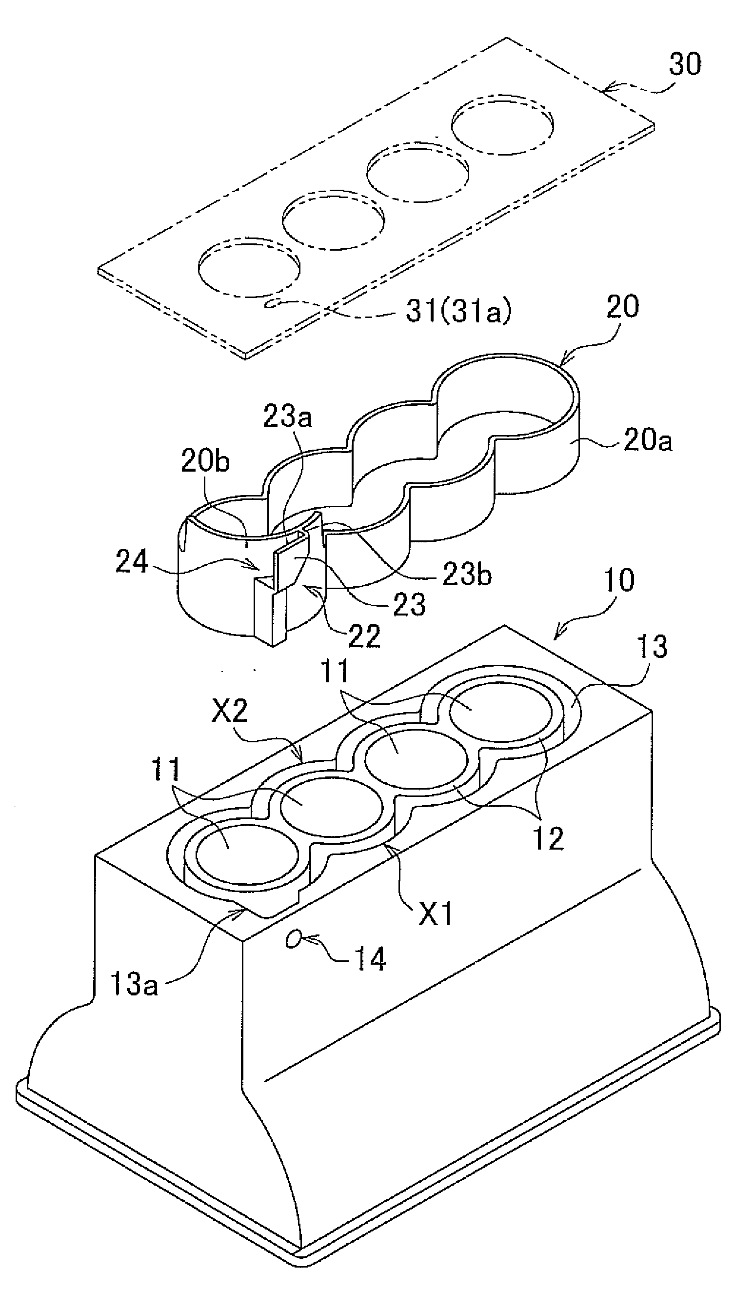
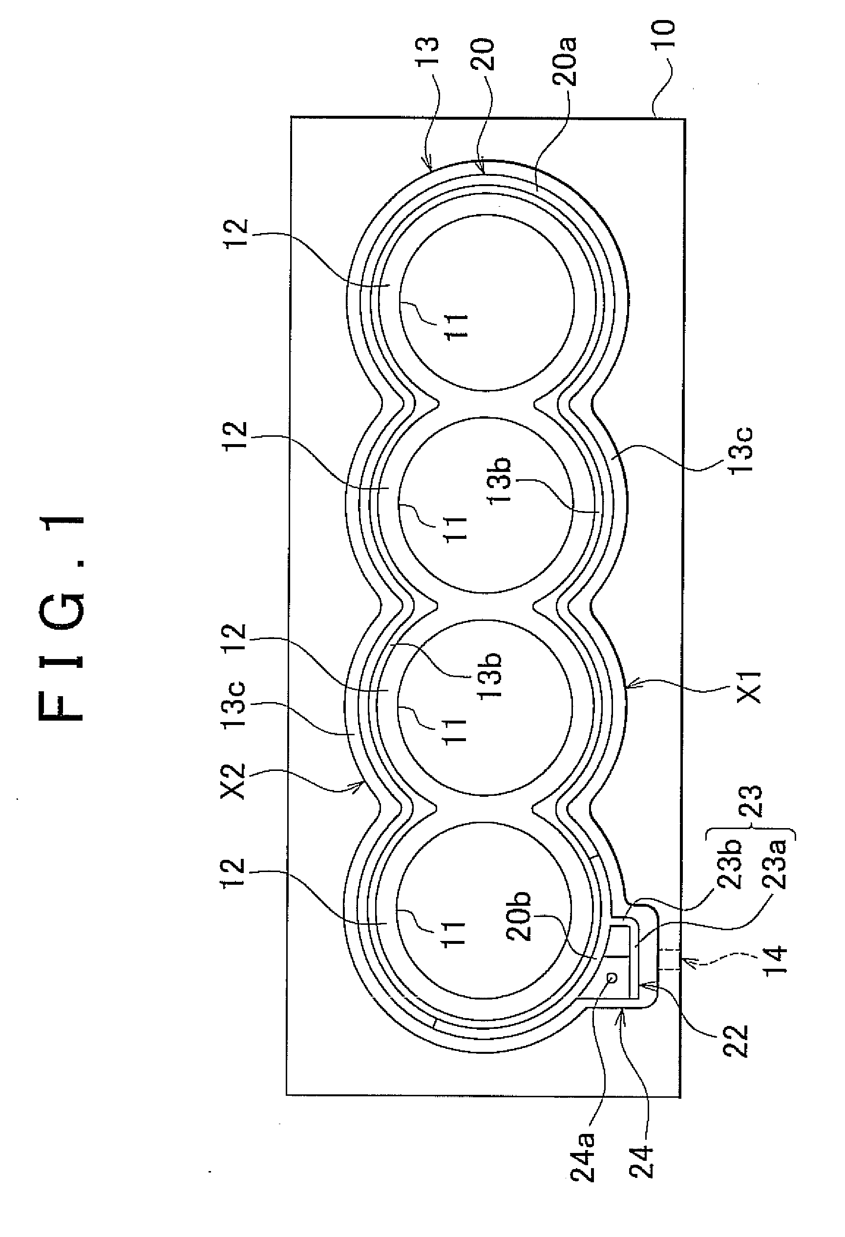
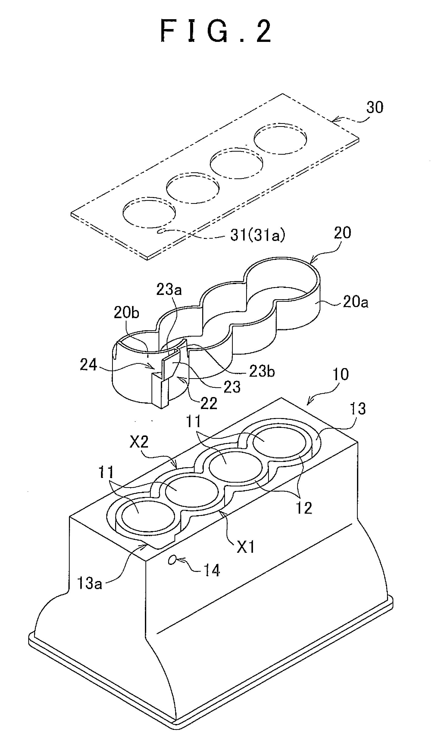
[0030]FIG. 1 is a plan view (a view from a direction perpendicular to a top surface of a water jacket 13) illustrating a schematic configuration of a cylinder block 10 in an internal combustion engine (engine) of the first embodiment. FIG. 2 is a perspective view illustrating the disassembled state the cylinder block 10 and a spacer 20 shown in FIG. 1. FIG. 1 shows an engine cylinder bore 11 of the cylinder block 10 and a peripheral portion thereof and illustrates a disposition state of a cylinder bore row, a water jacket (cooling water passage) 13, and...
PUM
 Abstract
Description
Claims
Application Information