Fuel injector

Inactive Publication Date: 2009-10-29
ROBERT BOSCH GMBH
View PDF0 Cites 7 Cited by
  • Summary
  • Abstract
  • Description
  • Claims
  • Application Information

AI Technical Summary

Benefits of technology

[0016]According to another advantageous embodiment, the injector housing includes a hydraulic coupling chamber that is acted on with the pressure of the high-pressure fuel source and hydraulically couples the piezoelectric actuator to the first end surface of the valve piston. The piezoelectric actuator can, for example, have an essentially circular, cylindrical head composed of metal attached to it, whose end surface delimits the hydraulic coupling chamber. On the opposite side, the hydraulic coupling chamber is preferably delimited by a first end surface of the valve piston. The hydraulic coupling chamber serves to c

Problems solved by technology

Activation of the pressure booster, however, requires a switching valve that activates a servo valve piston, which requires a significant structural complexity.
In the known embodiments of fuel injectors of interest here,

Method used


Image

  • Fuel injector
  • Fuel injector
  • Fuel injector

Examples


Example

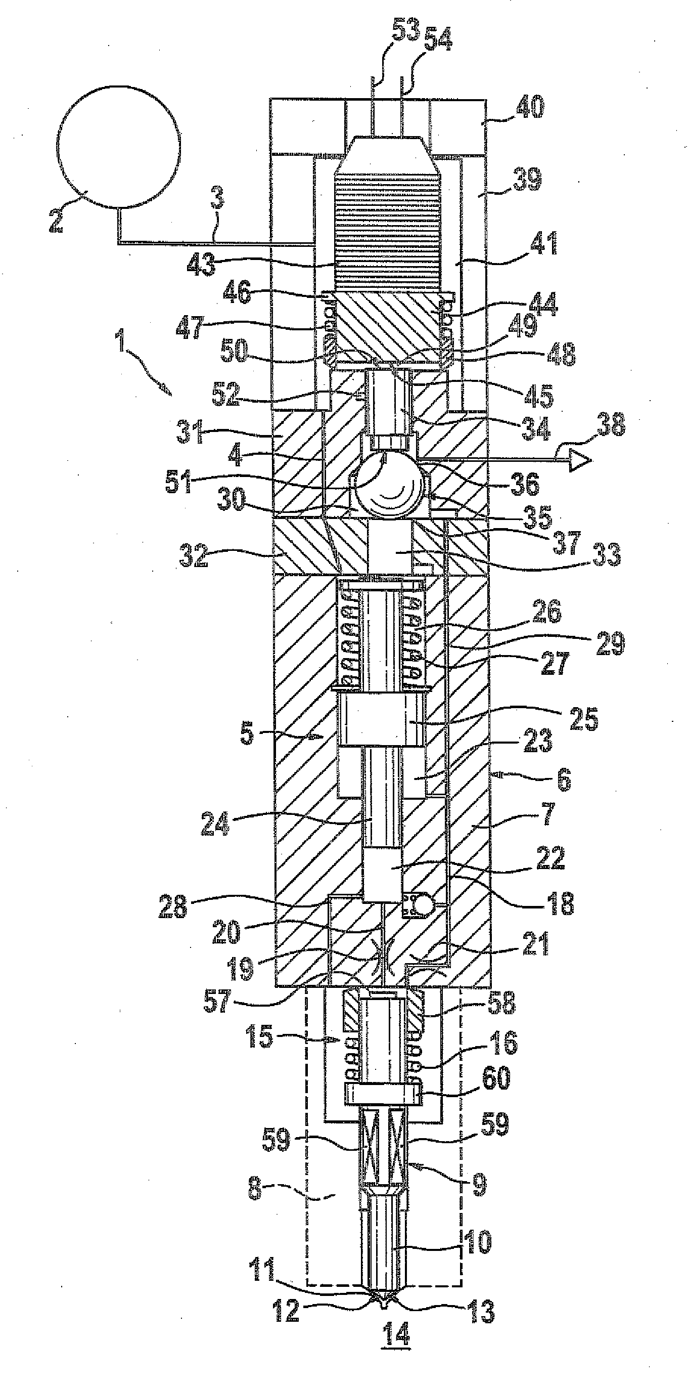
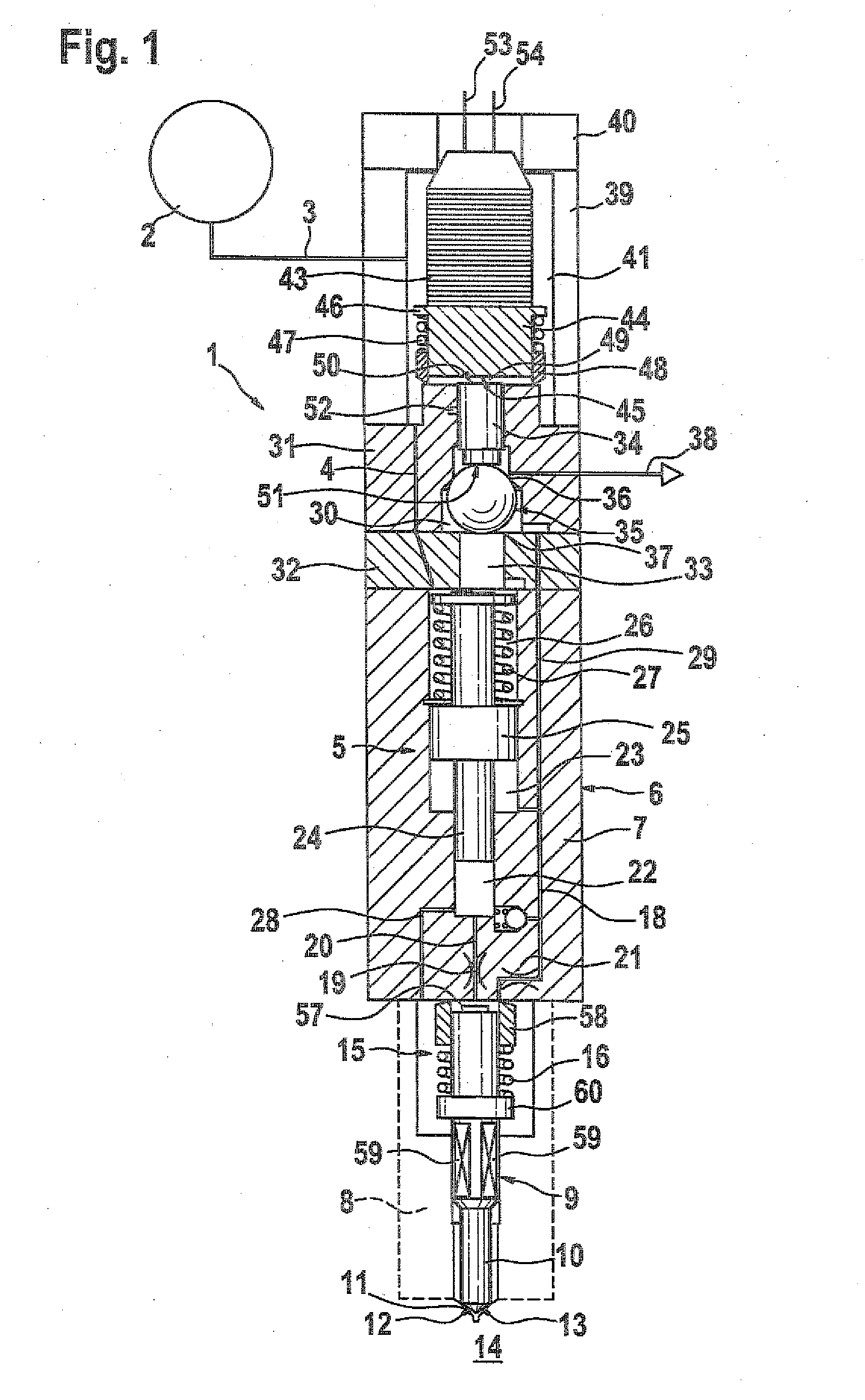
[0020]FIG. 1 shows a first exemplary embodiment of a fuel injector with a 3 / 2-way directional control valve, which has a ball element as a sealing body, in which the device includes a pressure booster and

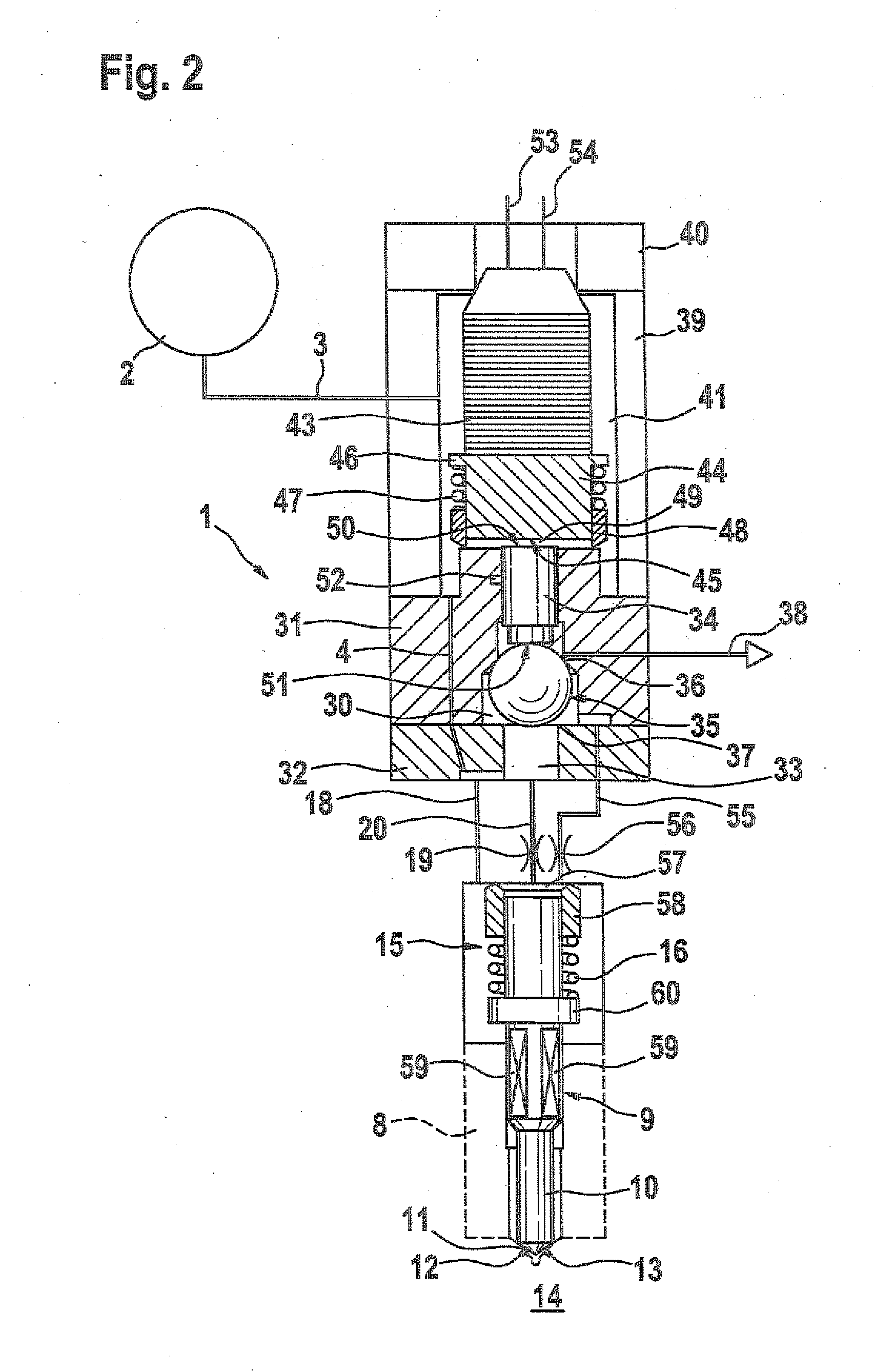
[0021]FIG. 2 shows another exemplary embodiment of a fuel injector according to FIG. 1, in which the device is embodied without a pressure booster.

[0022]FIG. 1 shows a longitudinal section through a fuel injector 1 that is supplied with highly pressurized fuel by a schematically depicted high-pressure source 2 (common rail). From the inner chamber of the high-pressure source 2, a fuel line 3, 4 extends to a pressure booster 5, which is integrated into the fuel injector 1. The pressure booster 5 is enclosed by an injector housing 6. The injector housing 6 includes an injector body 7 and a nozzle body 8 that has a central guide bore 9. A nozzle needle 10 is contained so that it is able to move back and forth in the guide bore 9. The nozzle needle has a tip 11 on which a sealing surfac...


PUM


Abstract

The invention relates to a fuel injector for injecting fuel into a combustion chamber of an internal combustion engine. A fuel supply line enters an injector housing from a high pressure fuel source which can be hydraulically connected to a pressure chamber. A 3/2 directional control valve for injecting fuel into the combustion chamber has a valve piston which can be moved axially back and forth between a rest position and an injection position. The 3/2 directional control valve, by a first end face of the valve piston, which adjoins a hydraulic coupling chamber, is hydraulically coupled to and can be activated by a piezoelectric actuator. The 3/2 directional control has a ball element which is connected to a second end face of the valve piston and, in the rest position, can be moved against a first sealing edge and, in the injection position, can be moved against a second sealing edge. The diameter of the valve piston and the diameter of the first sealing edge have a ratio which permits the ball element to be pressed in the rest position with a small contact force against the first sealing edge. A fuel injector with a 3/2 directional control valve is therefore created which has a simple design, and complex production processes are dispensed with.

Description

PRIOR ART[0001]The present invention relates to a fuel injector according to the preamble to claim 1.[0002]Fuel injectors of the type that is of interest here are particularly used in internal combustion engines that use such injectors to enable the metered injection of the fuel to be combusted.[0003]DE 103 25 620 A1 has disclosed a servo valve-controlled fuel injector with a pressure booster. The fuel injector disclosed therein includes a pressure booster, whose booster piston divides a working chamber, which is acted on with fuel by means of a pressure accumulator, from a differential pressure chamber, which can be pressure-relieved. A pressure change in the differential pressure chamber occurs through an actuation of the servo valve, which opens or closes a hydraulic connection of the differential pressure chamber to a first low-pressure side return. The servo valve also has a servo valve piston guided between a control chamber and a first hydraulic chamber. This servo valve pist...

Claims


Application Information

Patent Timeline
IPC IPC(8): F02M51/00
CPCF01N2560/025F02M47/027F02M57/025F02M61/167F02M61/188F02M63/0007F02M2547/001F02M63/004F02M63/0045F02M2200/703F02M2200/9007F02M2200/9053F02M63/0026
Inventor EISENMENGER, NADJAMENNICKEN, MICHAELMAGEL, HANS-CHRISTOPH
Owner ROBERT BOSCH GMBH
Why Eureka
Try Eureka