Charge/Discharge Control Device and Charge/Discharge Control Method for Power Storage Device, and Electric-Powered Vehicle

a power storage device and control device technology, applied in the direction of electric devices, propulsion parts, propulsion using engine-driven generators, etc., can solve the problems of not being able to obtain the best performance from the battery, and difficulty in accurately setting the relaxed level of charge/discharge limitation allowed exclusively for short time, etc., to achieve accurate charge/discharge

Inactive Publication Date: 2009-10-29
TOYOTA JIDOSHA KK
View PDF11 Cites 57 Cited by
  • Summary
  • Abstract
  • Description
  • Claims
  • Application Information

AI Technical Summary

Benefits of technology

[0023]With such a configuration, in the electric-powered vehicle (a hybrid motor vehicle or the like) mounted with the internal combustion engine, the power storage device, and the electric motor configured to be able to receive electric power from and transmit electric power to the power storage device in a bidirectional manner, and in a driving circumstance where an absolute value of the regenerative torque requested from the electric motor is larger than a prescribed value and a charge request to the power storage device is larger relative to that in a normal state, such as when the brake is manipulated during high-speed running, or when a deceler

Problems solved by technology

However, in the configurations disclosed in Patent Documents 1 and 2, a battery voltage at each time point, which momentarily varies, is not considered, and hence it is difficult to accurately set a relaxed level of charge/discharge limitation permitted exclusively for short time, within a range from a lower limit voltage to an upper limit voltage.
Therefore, depending on a charge/discharge history by that point in time, the battery voltage may be excessively lowered, an

Method used


Image

  • Charge/Discharge Control Device and Charge/Discharge Control Method for Power Storage Device, and Electric-Powered Vehicle
  • Charge/Discharge Control Device and Charge/Discharge Control Method for Power Storage Device, and Electric-Powered Vehicle
  • Charge/Discharge Control Device and Charge/Discharge Control Method for Power Storage Device, and Electric-Powered Vehicle

Examples


Embodiment Construction

[0031]An embodiment of the present invention will hereinafter be described in detail with reference to the drawings. Note that the same or corresponding portions in the drawings are provided with the same reference characters in the following and the description thereof will not be repeated in principle.

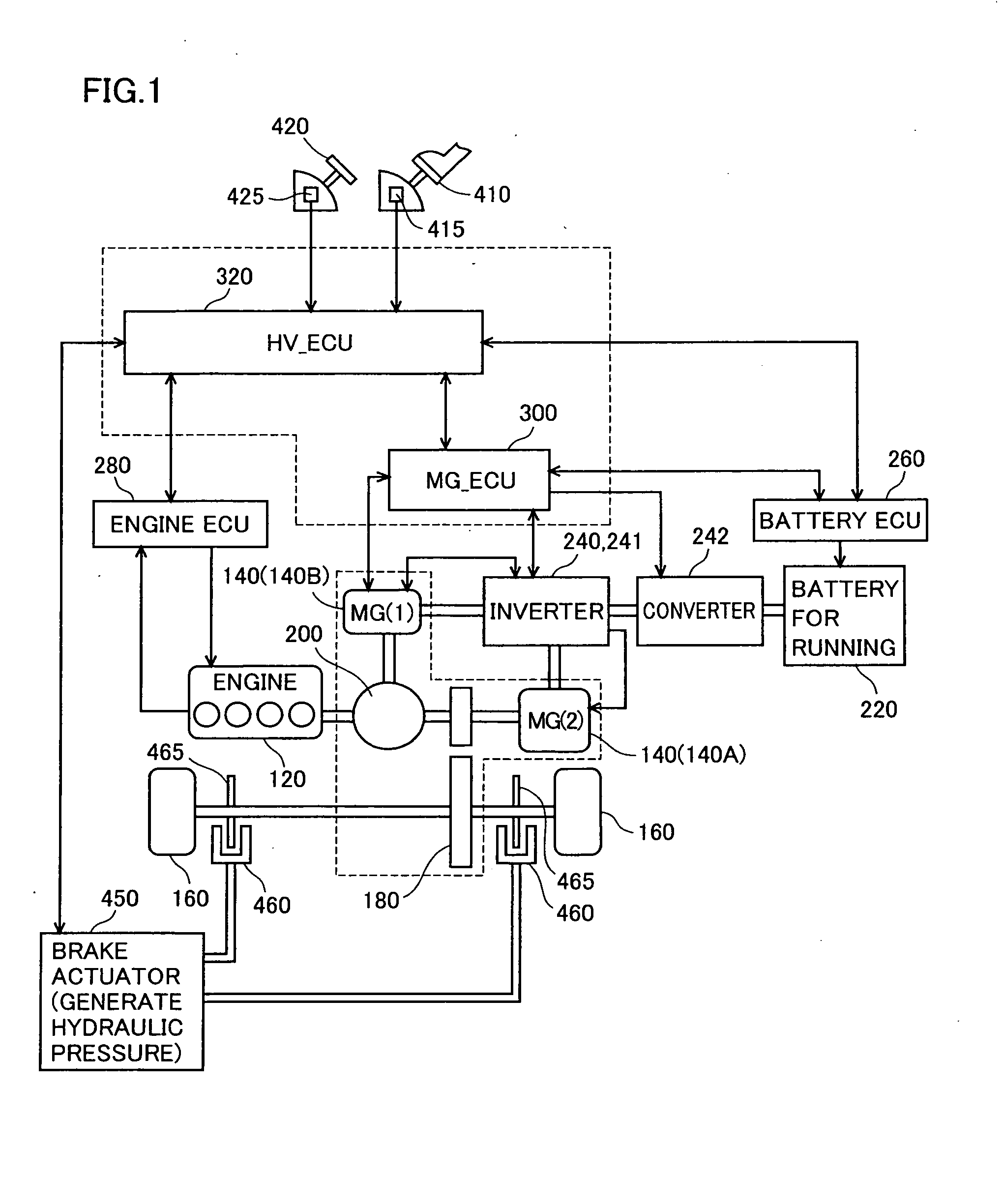
[0032]FIG. 1 is a control block diagram of a hybrid vehicle shown as a representative example of an electric-powered vehicle mounted with a control device for a power storage device according to an embodiment of the present invention. Note that the electric-powered vehicle is not limited to the hybrid vehicle shown in FIG. 1, and the present invention may also be applied to a hybrid vehicle of another mode (e.g. a series-type hybrid vehicle) or an electric vehicle, as long as the vehicle is configured to be able to recover energy caused by regenerative power generation during deceleration of the vehicle and store the same in the power storage device.

[0033]In the present embodiment be...


PUM


Abstract

A maximum dischargeable current Idmax obtained when electric power output from a battery is increased from a battery current Ib and a battery voltage Vb at present under internal resistance R at present (an operating point 510) until the battery voltage reaches a lower limit voltage Ve (an operating point 520), is shown as follows: Idmax=Ib+(Vb−Ve)/R. Therefore, in accordance with multiplication of the lower limit voltage Ve and the maximum dischargeable current Idmax, it is possible to predict maximum dischargeable electric power at which the battery voltage does not become lower than the lower limit voltage even if discharge limitation is temporarily relaxed, as a relative value with respect to the battery voltage and the battery current at present. When the discharge electric power limitation for the battery (the power storage device) is temporarily relaxed in accordance with a discharge request made by a load, a discharge electric power permissible value is set to correspond to the maximum dischargeable electric power, such that the output voltage of the power storage device does not fall outside a controlled voltage range from the lower limit voltage to an upper limit voltage.

Description

TECHNICAL FIELD[0001]The present invention relates to a charge / discharge control device for a power storage device, a charge / discharge control method for a power storage device, and an electric-powered vehicle, and more specifically relates to charge / discharge control for maintaining an output voltage of the power storage device within a controlled voltage range from a lower limit voltage to an upper limit voltage.BACKGROUND ART[0002]There has widely been used a system that drives and controls an electrical apparatus serving as a load, while a power storage device, a typical example of which is a secondary battery (hereinafter also simply referred to as a battery), is being charged / discharged. For example, such a system is applied to a hybrid vehicle configured to include an engine, a motor generator that functions as an electric motor or an electric power generator, and a battery that receives electric power from and transmits electric power to the motor generator for charge / discha...

Claims


Application Information

Patent Timeline
IPC IPC(8): B60W10/04H02J7/00B60W20/00B60L50/15B60L50/16
CPCB60L11/123B60L11/14B60L11/1861H01M10/44H01M10/443H01M10/48Y02E60/12Y02T10/6217Y02T10/7005Y02T10/7022Y02T10/7044Y02T10/705Y02T10/7077H02J7/0057B60L3/0046B60L7/14B60L7/26B60L15/20B60L15/2009B60L2240/421B60L2240/423B60L2240/545B60L2240/547B60L2240/549B60L2260/44Y02T10/72B60L50/61B60L50/16B60L58/14B60L58/25B60L58/15H02J7/0069Y02T10/62Y02T10/64Y02T10/70Y02T10/7072Y02E60/10B60Y2200/91B60Y2200/92B60L58/13B60K1/02B60K6/26B60K6/24
Inventor KIKUCHI, YOSHIAKI
Owner TOYOTA JIDOSHA KK
Why Eureka
Try Eureka