Because of this, the lower hoop member needs to be adjusted for any change in thickness of the item to be hooped, which may not always result in the material being sufficiently taut or tight, potentially resulting in an improperly embroidered piece of material.
The use of standard embroidery hoops becomes more difficult when the item to be embroidered is a heavier or thicker material, such as a winter jacket, work overalls, Carhartt® type jackets, or items made of leather.
Properly embroidering such items can be very difficult and
time consuming.
It is very difficult to figure out what adjustment should be made to the lower hoop or clamping member to securely hold the garment, while not having too tight of an arrangement that the two clamping members cannot properly mate with one another.
It often takes multiple tries to get the adjustment correct.
These clamping members are spring loaded to allow for different thickness of material to be held without adjustment, but they do have limitations.
One of the main limitations of the prior art is how far from an edge of a garment that it can hold a portion of fabric to be embroidered.
The arrangement makes placing a logo in the middle of the back of a jacket, or on the left or
right chest of a garment very difficult.
If the distance to the logo location is larger than the distance from the clamping members to the pivot point, the material will need to be gathered in the pivot point to reach the embroidery location, which is usually impossible or impractical for these types of hooping machines.
Other problems arise when using computerized embroidery machines, since the position and orientation of the embroidery on the item is a function of how the item is captured within the hoop.
Items to be embroidered are usually placed directly within the clamps while they are mounted on the embroidery
machine, as it is difficult and
time consuming to remove and reinstall the clamps onto the
machine.
This creates extra
downtime for the machine, since it is not possible to have the next set of items hooped and ready to load onto the embroidery machine.
Mounting the fabric in the clamps while they are attached to the machine also makes aligning the exact portion of the garment to be embroidered very difficult.
Even if the clamp were removed from the machine, there are no commercially available hooping devices or jigs to help align the clamp with a particular portion of a garment.
Because of the need for a pivot point and at least one spring for biasing the base plate and upper clamping member in closed contact, the maximum sewing area of the embroidery machine is further limited by this prior art space requirement.
Such rigid material, and the extra mechanism needed for the pivot point and spring bias, makes the clamps heavier than standard hoops, with the added weight applying unnecessary stress to the mechanical and electrical components of the embroidery machine.
The physical size of the clamp can also cause damage to some embroidery machines if the entire body of the clamp cannot fit under the needle bars used for embroidery.
This type of frame is very good for getting into small areas like pockets on garments, or for sewing on delicate fabrics, but is not really designed for everyday normal hooping of garments; it is more for
specialty items.
One
disadvantage to these frames is the need for special sticky backing, which is generally more expensive than standard backing and can leave a residue on the needles of the embroidery machine over time.
The residue can cause increased thread breaks and other problems.
Also, the backing material has a limited number of uses before it needs to be removed from the frame and a new piece applied, which can increase the production time needed to complete a job.
The sticky backing is not strong enough to adequately hold heavy items like Carhartt® type jackets during the embroidery process.
The extra expense and increase in production time that is created by the use of sticky backing makes the sticky backing type of frame impractical for most normal placements of designs on shirts and jackets.
The hoop from this prior art device is not designed to be releasably mounted to the existing hoop holding arms on these newer style commercial embroidery machines.
This outdated design increases the time it takes to switch from using one type of frame to another.
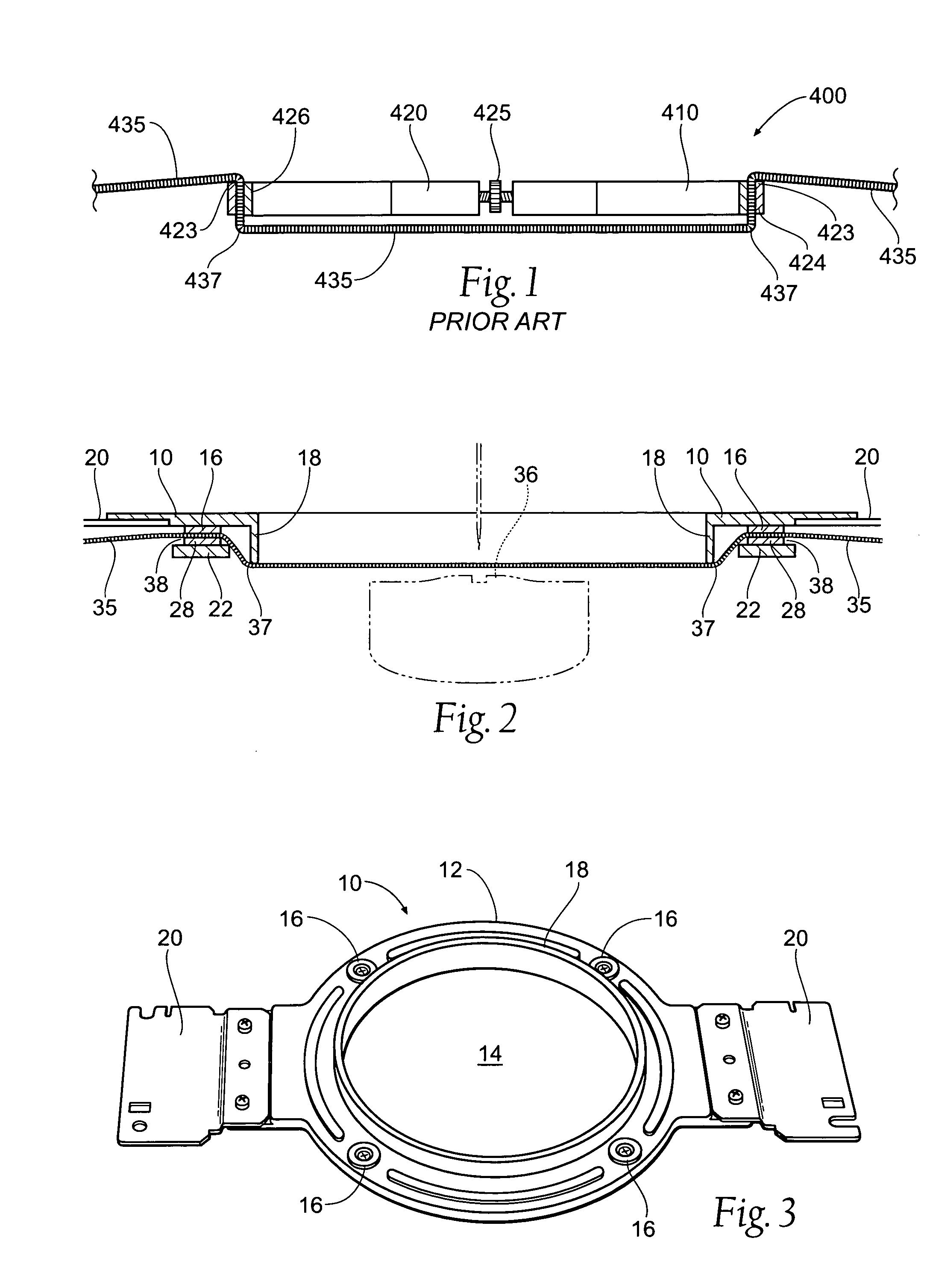
This type of magnetic material arrangement does not provide any automatic alignment between the upper and lower members of the frame.
The frame of this prior art device pinches the material directly between the magnetic materials; it also does not provide a
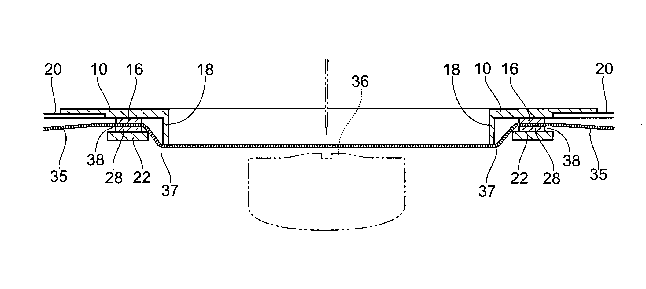
ridge to help hold the material to be embroidered taut and against the needle plate of the embroidery machine.
If the material to be embroidered is not held taught and against the needle plate, this causes bouncing of the material during the embroidery process.
This bouncing can cause looping of the embroidery thread and an undesirably look of the finished embroidery.

