
Electromagnetic exciter

Inactive Publication Date: 2009-10-29
CITIZEN ELECTRONICS CO LTD +1
View PDF10 Cites 71 Cited by
  • Summary
  • Abstract
  • Description
  • Claims
  • Application Information

AI Technical Summary

Benefits of technology

[0024]The permanent magnet of the oscillator may be secured to a part of the magnetic pole member.
[0025]The permanent magnet of the oscillator ma

Problems solved by technology

A vibration-generating device with such a structure, however, has a circular cylindrical configuration as a whole due to the cylindrical motor configuration and the rotary weight configurations and is therefore unsuitable for thickness reduction.
Further, because the eccentric weight is rotated to generate vibration, the rotating shaft is subjected to an excessive stress, which gives rise to problems in terms of durability and reliability.
The electromagnetic coil of the electromagnet block generates an alternating magnetic field in response to an alternating current applied to the coil of the electromagnet block, thus causing oscillation of the permanent magnet block to generate vibration.
Therefore, the height of the electromagnetic exciter increases, making it difficult to reduce the thickness of a mobile device into which the electromagnetic exciter is incorporated.

Method used


Image

  • Electromagnetic exciter
  • Electromagnetic exciter
  • Electromagnetic exciter

Examples


Embodiment Construction

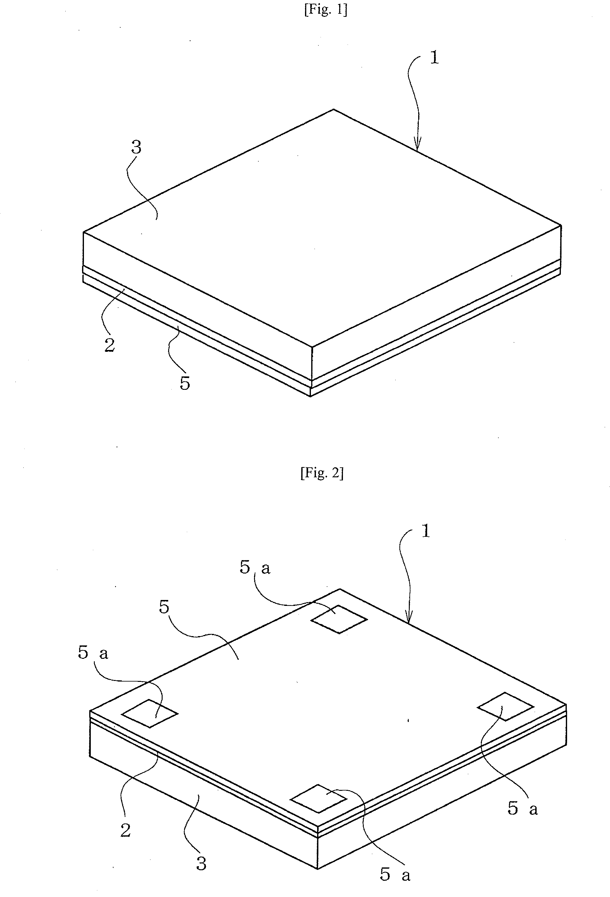
[0081]FIGS. 1 to 13 show an electromagnetic exciter 1 according to a first embodiment of the present invention. The electromagnetic exciter 1 has a flat casing comprising a lower casing member 2 and an upper casing member 3. The electromagnetic exciter 1 further has a vibration generating part set in the casing. A circuit board 5 is mounted on the bottom of the lower casing member 2. Connection to an external circuit is made through external connection terminals 5a provided at four corners of the circuit board 5.

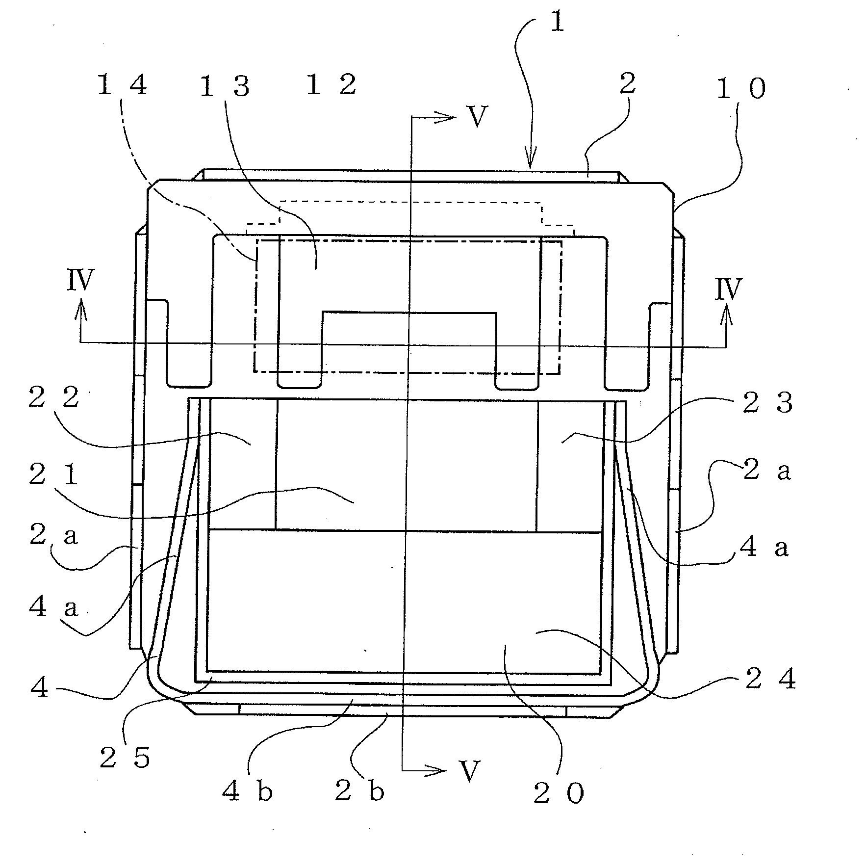
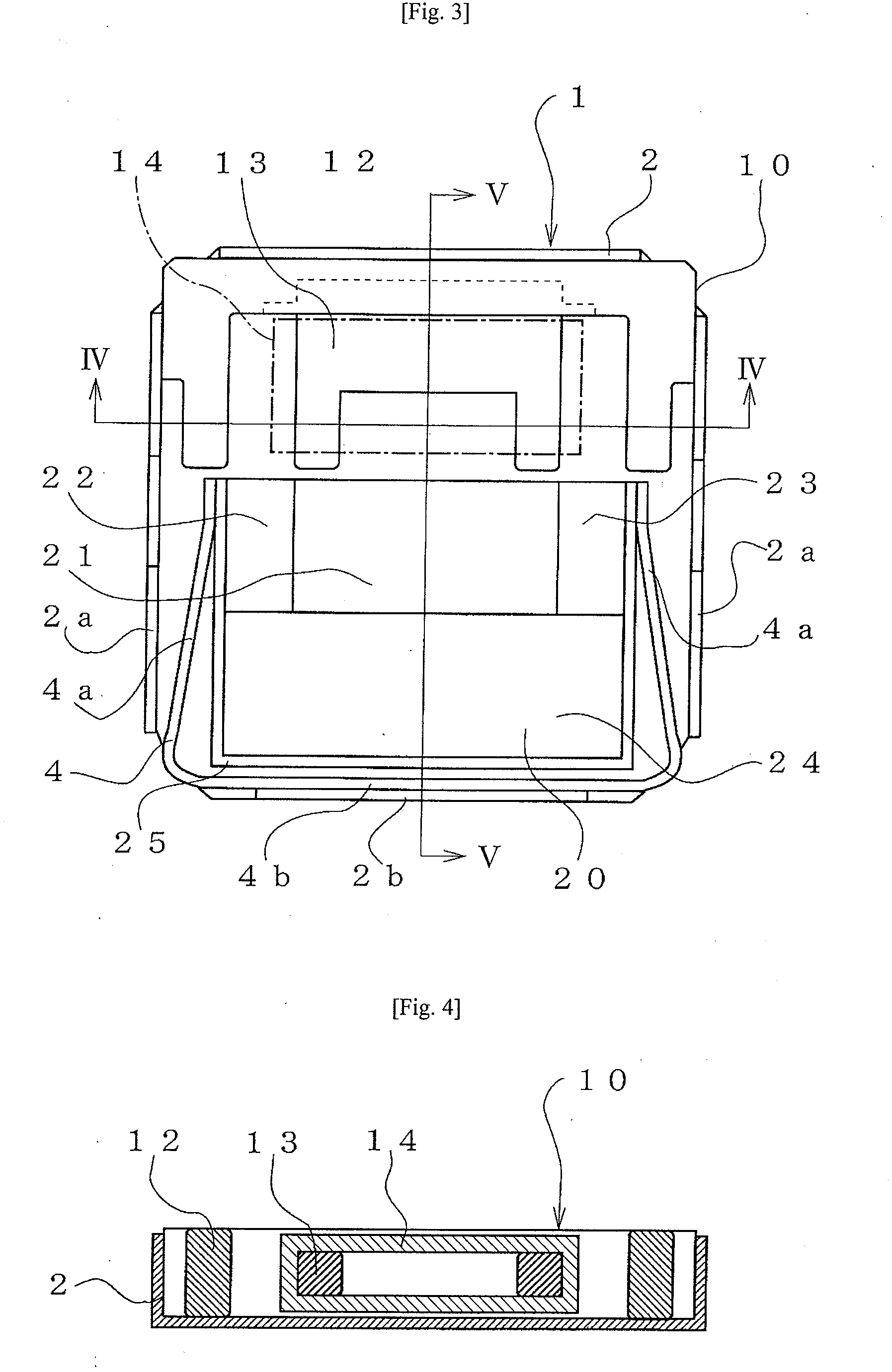
[0082]FIG. 3 is a plan view showing the electromagnetic exciter 1 in FIG. 1 with the upper casing member 3 removed to allow the vibration generating part of the electromagnetic exciter 1 to be seen. In the lower casing member 2, a stator 10 and an oscillator 20 are horizontally opposed. The stator 10 comprises a yoke member 12, a pole piece 13, and an electromagnetic coil 14 (see FIGS. 7 to 9) and is secured to the lower casing member 2 by bonding or welding, for example. Th...


PUM


Abstract

An electromagnetic exciter that enables thickness reduction has a casing, a stator having an electromagnet and fixed in the casing, an oscillator having a permanent magnet, and an elastic support member that positions the oscillator in horizontally-opposed relation to the stator at a distance between them and that supports the oscillator oscillatably in a direction parallel to the stator. The elastic support member has a fixed portion fixed to the casing and a pair of arms extending from the fixed portion toward the stator along side surfaces of the oscillator to support the oscillator oscillatably. The oscillator is oscillated by an alternating magnetic field generated by application of an alternating voltage to the electromagnet of the stator.

Description

[0001]This application claims priority under 35 U.S.C. §119 to Japanese Patent application No. JP2008-112026 filed on Apr. 23, 2008, Japanese Patent application No. JP2008-134658 filed on May 22, 2008, Japanese Patent application No. JP2008-178633 filed on Jul. 9, 2008, Japanese Patent application No. JP2008-280390 filed on Oct. 30, 2008, Japanese Patent application No. JP2008-290299 filed on Nov. 12, 2008, and Japanese Patent application No. JP2009-003850 filed on Jan. 9, 2009, the entire contents of which are hereby incorporated by reference.TECHNICAL FIELD[0002]The present invention relates to an electromagnetic exciter that can be incorporated in thin mobile devices such as mobile phones.RELATED ART[0003]Conventionally, thin mobile devices such as mobile phones generate ringtones to indicate an incoming call or a schedule and additionally have a vibration-generating device to inform the user of an incoming call or the like by vibration in trains or at meetings where noises shoul...

Claims


Application Information

Patent Timeline
IPC IPC(8): H02K33/00
CPCH02K33/16H02K33/02
Inventor KAJIWARA, HIROOMIURA, NAOKI
Owner CITIZEN ELECTRONICS CO LTD
Features
  • Generate Ideas
  • Intellectual Property
  • Life Sciences
  • Materials
  • Tech Scout
  • Unparalleled Data Quality
  • Higher Quality Content
  • 60% Fewer Hallucinations
Learn More