Image forming apparatus and image forming method
a technology of image forming and forming apparatus, which is applied in the direction of printing mechanism, spacing mechanism, printing, etc., can solve the problems of difficult to solve the above-described problems of printer, suppress the density non-uniformity, and the density of a formed image becomes non-uniform
- Summary
- Abstract
- Description
- Claims
- Application Information
AI Technical Summary
Benefits of technology
Problems solved by technology
Method used
Image
Examples
first embodiment
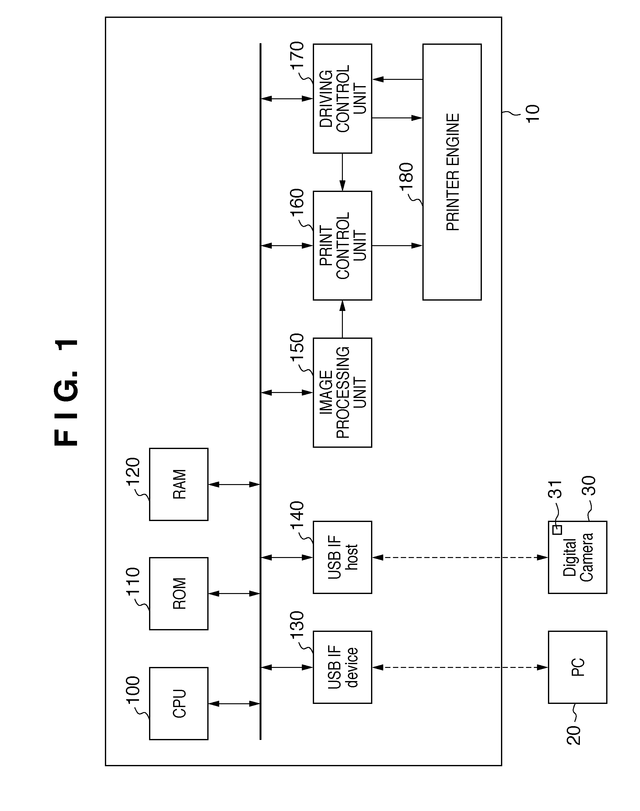
[0064]FIG. 1 is a block diagram showing the functional arrangement of a printer 10 according to the first embodiment.
[0065]In the first embodiment, the printer 10 is an inkjet printer. The printer 10 includes a CPU (Central Processing Unit) 100, ROM 110, RAM 120, USB device interface (I / F) 130, and USB host interface (I / F) 140. The printer 10 also includes an image processing unit 150, print control unit 160, driving control unit 170, and printer engine 180.
[0066]The CPU 100 controls the printer 10. The ROM 110 stores programs and table data for the CPU 100. The RAM 120 is a memory for storing variables and data.
[0067]The USB device interface 130 receives data from a personal computer (PC) 20. The USB host interface 140 receives data from an electronic device such as a digital camera 30. In the first embodiment, the personal computer 20 is connected to the USB device interface 130 while the digital camera 30 is connected to the USB host interface 140.
[0068]The image processing unit ...
first modification to first embodiment
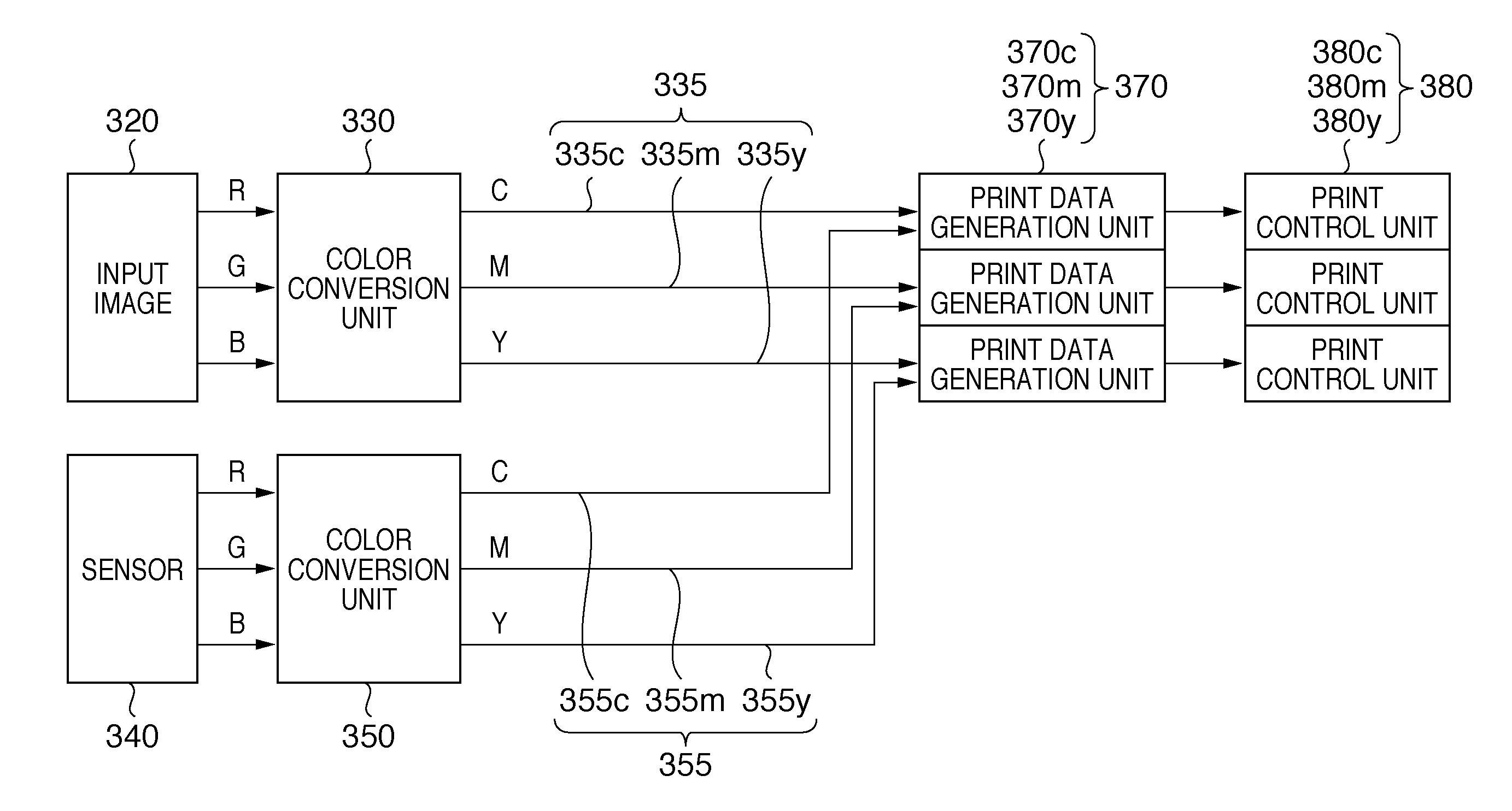
[0122]FIG. 7 is a block diagram showing the functional arrangement of the print data generation unit 370 according to the first modification to the first embodiment.
[0123]The multiplier 420 divides the print image signal 400 into the densities of the respective passes on the basis of an input from the pass division table 410. Based on the signal 430 detected by the sensor 340, the print data control unit 440 controls print data of the print image of each pass having undergone density division by the multiplier 420. Under the control of the print data control unit 440, the tone reduction unit 450 reduces the tone of the print data having undergone pass division by the multiplier 420. The print image storage 460 stores the print data of each pass having undergone tone reduction by the tone reduction unit 450.
[0124]In accordance with the print image signal 400 which has been converted into a C, M, or Y signal, and the signal 430 which has been detected by the sensor 340 and converted i...
second modification to first embodiment
[0125]The first embodiment adopts an RGB saturated color filter as the sensor 340. Instead, a CMY complementary color filter can also be used like the second modification.
[0126]FIG. 8 is a block diagram showing the functional arrangement of an image forming apparatus according to the second modification to the first embodiment. FIG. 14 is a view showing the positions of dots formed in the respective passes in the second modification to the first embodiment. In FIG. 14, ◯ represent dots formed on a print medium, and numerals “1”, “2”, “3”, and “4” in o represent the numbers of scan operations which formed dots.
[0127]In this case, a printing state detected by a sensor 342 is input to a color conversion unit 352 not as R, G, and B signals as shown in FIG. 3, but as C, M, and Y signals representing signals C′, M′, and Y′, as shown in FIG. 8. The color conversion unit 352 converts the signals C′, M′, and Y′ input from the sensor 342 into signals C, M, and Y representing the ink colors. E...
PUM
 Abstract
Description
Claims
Application Information
 - R&D
- Intellectual Property
- Life Sciences
- Materials
- Tech Scout
- Unparalleled Data Quality
- Higher Quality Content
- 60% Fewer Hallucinations
Browse by: Latest US Patents, China's latest patents, Technical Efficacy Thesaurus, Application Domain, Technology Topic, Popular Technical Reports.
© 2025 PatSnap. All rights reserved.Legal|Privacy policy|Modern Slavery Act Transparency Statement|Sitemap|About US| Contact US: help@patsnap.com


