Image pickup apparatus and endoscope

a technology of endoscope and pickup apparatus, which is applied in the field of image pickup apparatus and endoscope, can solve problems such as the increase of the number

Inactive Publication Date: 2009-10-29
OLYMPUS CORP
View PDF10 Cites 61 Cited by
  • Summary
  • Abstract
  • Description
  • Claims
  • Application Information

AI Technical Summary

Problems solved by technology

However, downsizing of the package unit and increase in the number of electronic components mounted on the FPC pose a problem in that the FPC disposed behind the solid-state image pickup device chip juts out greatly from the package unit when seen in planar view from the image pickup surface.

Method used


Image

  • Image pickup apparatus and endoscope
  • Image pickup apparatus and endoscope
  • Image pickup apparatus and endoscope

Examples


first embodiment

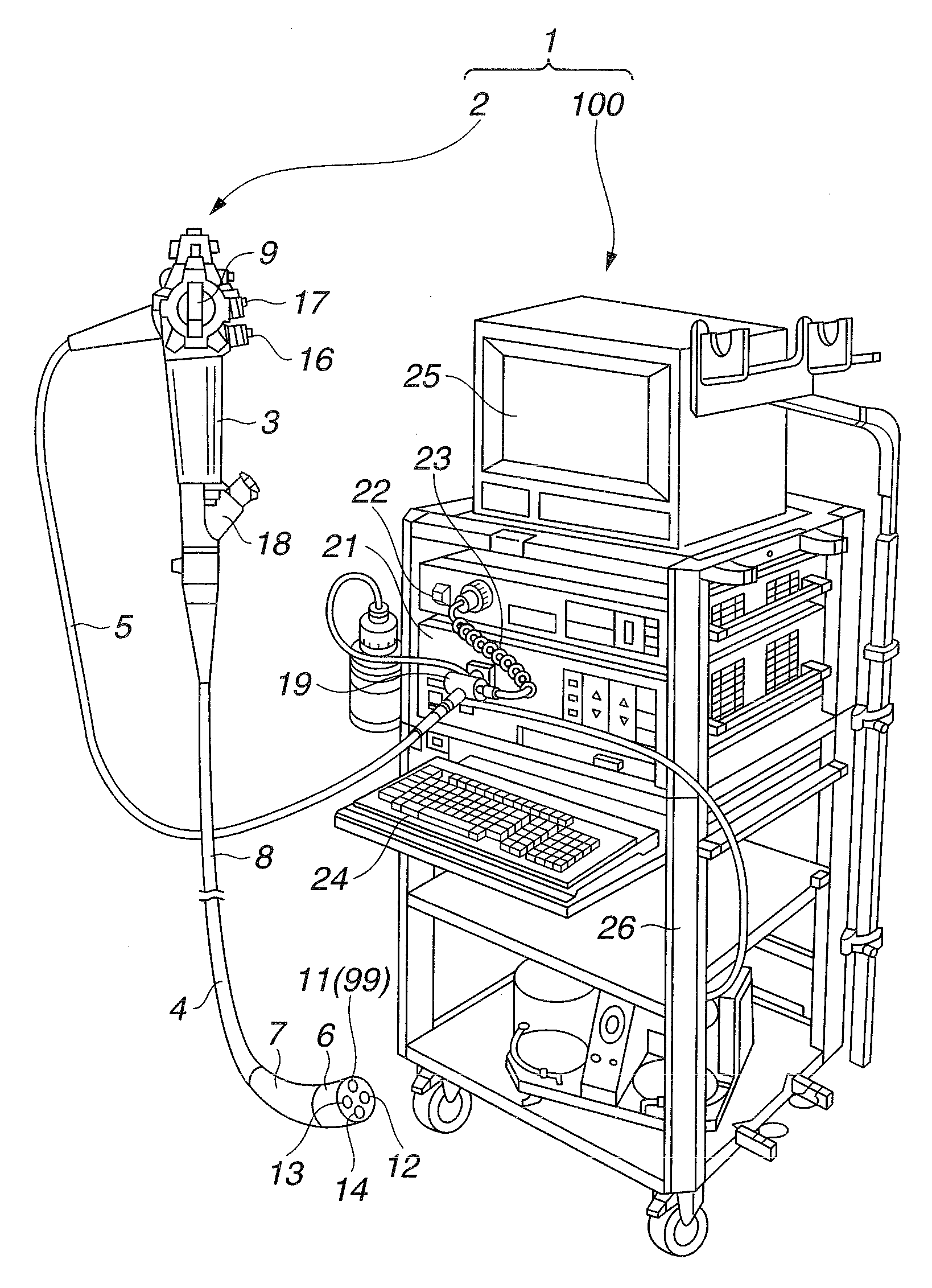
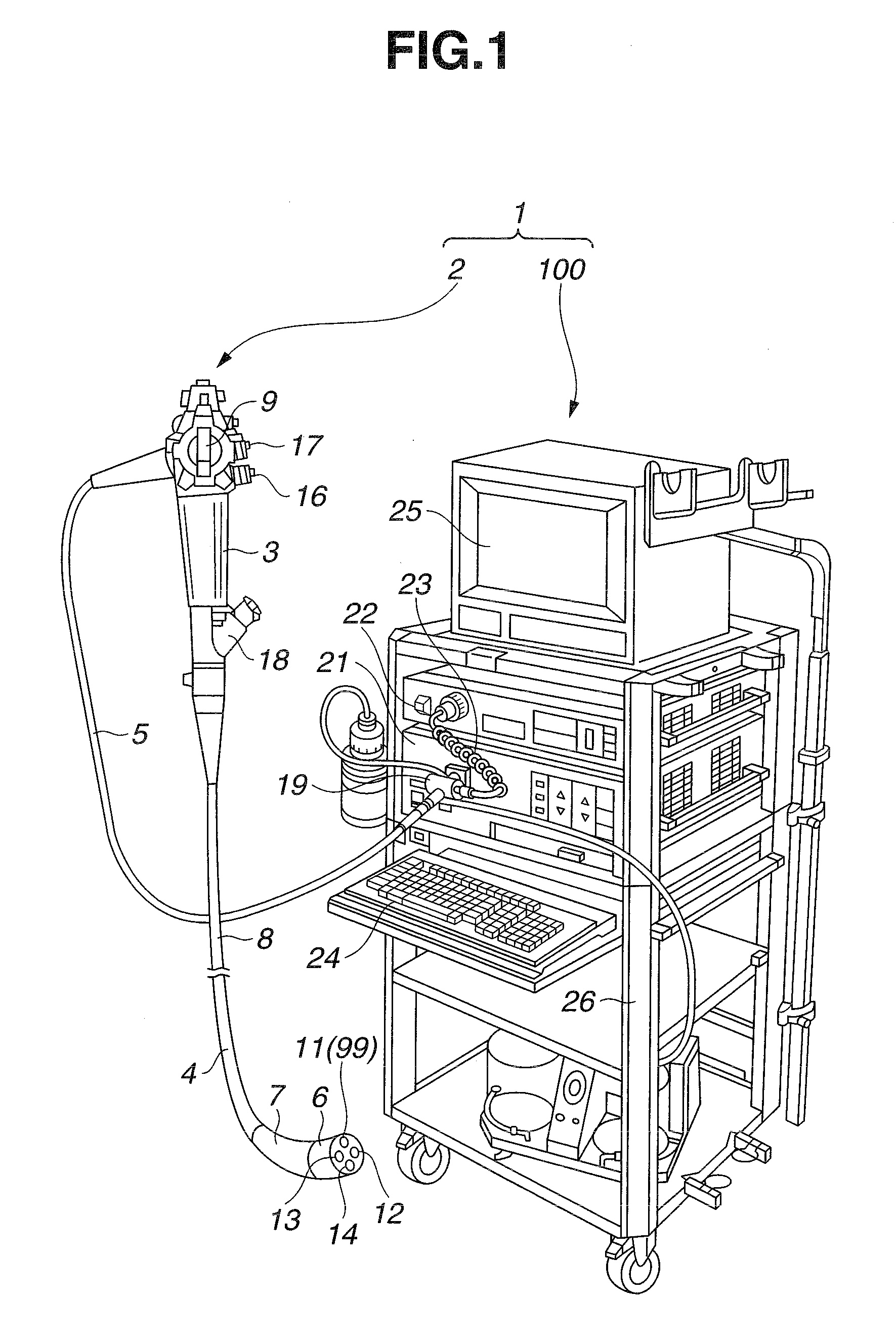
[0027]FIG. 1 is an external perspective view showing an endoscope apparatus which includes an endoscope and peripheral apparatus, where the endoscope includes an image pickup apparatus according to the present embodiment.

[0028]As shown in FIG. 1, the endoscope apparatus 1 includes the endoscope 2 and peripheral apparatus 100. Principal part of the endoscope 2 includes an operation portion 3, insertion portion 4, and universal cord 5.

[0029]Principal part of the peripheral apparatus 100 includes, a light source 21, video processor 22 which is an external apparatus, connection cable 23, keyboard 24, and monitor 25, all of which are placed on a rack 26. The endoscope 2 and peripheral apparatus 100 configured as described above are interconnected via a connector 19.

[0030]The operation portion 3 of the endoscope 2 is provided with a bending operation knob 9, air / water supply button 16, suction button 17, and treatment instrument insertion port 18.

[0031]The insertion portion 4 of the endos...

second embodiment

[0100]FIG. 6 is a diagram showing part of an image pickup apparatus according to the present embodiment. FIG. 7 is an exploded plan view showing an FPC in FIG. 6.

[0101]A configuration of the image pickup apparatus according to the second embodiment differs from the image pickup apparatus according to the first embodiment shown in FIGS. 1 to 4 in that lead wire connecting portions are installed on a rear side of the FPC. Only the difference will be described. On the other hand, the same components as the first embodiment will be denoted by the same reference numerals as the corresponding components in the first embodiment, and description thereof will be omitted.

[0102]As shown in FIG. 7, a seventh region 57 is provided on the right side of the second region 52 of the FPC 43 in FIG. 7 via a deformation portion 156 and the lead wire connecting portion 73 is provided on the rear surface 43t of the FPC 43 in the seventh region 57. The deformation portion 156 has a smaller surface area th...

third embodiment

[0117]FIG. 8 is a diagram showing part of an image pickup apparatus according to the present embodiment and FIG. 9 is an exploded plan view showing an FPC in FIG. 8.

[0118]A configuration of the image pickup apparatus according to the third embodiment differs from the image pickup apparatus according to the first embodiment shown in FIGS. 1 to 4 in that mounting surfaces for the electronic components are provided on the front surface of the FPC in four layers and that a mounting strength enhancement portion is provided in the second region. Only the differences will be described. On the other hand, the same components as the first embodiment will be denoted by the same reference numerals as the corresponding components in the first embodiment, and description thereof will be omitted.

[0119]As shown in FIG. 9, a ninth region 59 is provided above the fourth region 54 of the FPC 43 in FIG. 9 via a deformation portion 159. Also, a tenth region 60 is provided above the ninth region 59 in F...


PUM


Abstract

An image pickup apparatus includes a solid-state image pickup device chip, an FPC whose terminals are connected to the solid-state image pickup device chip, and a plurality of electronic components mounted on a front surface of the FPC, wherein behind a back face of the solid-state image pickup chip, the FPC is disposed by being folded in such a way that the FPC will provide mounting surfaces for the plurality of electronic components in a plurality of layers and that the plurality of electronic components will be superimposed via the FPC.

Description

CROSS REFERENCE TO RELATED APPLICATION[0001]This application is a continuation application of PCT / JP2007 / 069299 filed on Oct. 2, 2007 and claims benefit of Japanese Application No. 2007-007430 filed in Japan on Jan. 16, 2007, the entire contents of which are incorporated herein by this reference.BACKGROUND OF INVENTION[0002]1. Field of the Invention[0003]The present invention relates to an image pickup apparatus and endoscope equipped with a solid-state image pickup device chip, a flexible printed circuit board connected to the solid-state image pickup device chip at one end, and multiple electronic components mounted at least on one side of the flexible printed circuit board.[0004]2. Description of the Related Art[0005]In electronic endoscope apparatus which have come into widespread use in recent years, an image pickup apparatus which uses a solid-state image pickup device chip as image pickup means is disposed at a distal end of an insertion portion of an endoscope. In medical ap...

Claims


Application Information

Patent Timeline
Patent Type & Authority Applications(United States)
IPC IPC(8): H04N7/18H04N5/335A61B1/04G02B23/24G03B17/02H04N5/225
CPCA61B1/00124A61B1/051G02B23/2484G03B17/02A61B1/0008H04N2005/2255H05K1/189H05K2201/042H05K2201/10121H04N5/2253A61B1/005H04N23/555H04N23/54A61B1/00097
Inventor ISHII, HIROSHIISHIDA, YUYAKUMEI, KAZUHIROAKIBA, KAZUYOSHI
Owner OLYMPUS CORP
Why Eureka
Try Eureka