Optimised packet data transmission protocol in a communication system employing a transmission window

a transmission window and packet data technology, applied in the field of transmission and retransmission of packet data, can solve the problems of high error rate of wireless networks, low degree of packet error or loss tolerance, and inability to meet qos guarantees, so as to increase the likelihood of meeting qos guarantees

a transmission window and packet data technology, applied in the field of transmission and retransmission of packet data, can solve the problems of high error rate of wireless networks, low degree of packet error or loss tolerance, and inability to meet qos guarantees, so as to increase the likelihood of meeting qos guarantees

US20090268706A1Inactive Publication Date: 2009-10-29GOOGLE TECH HLDG LLC

Image

  • Optimised packet data transmission protocol in a communication system employing a transmission window
  • Optimised packet data transmission protocol in a communication system employing a transmission window
  • Optimised packet data transmission protocol in a communication system employing a transmission window

Examples


Embodiment Construction

[0029]The following description focuses on embodiments of the invention applicable to a cellular communication system providing real-time services utilizing GPRS. However, it will be appreciated that the invention is not limited to this application but may be applied to many other cellular communication systems utilizing services that may be adversely affected by transmission delays.

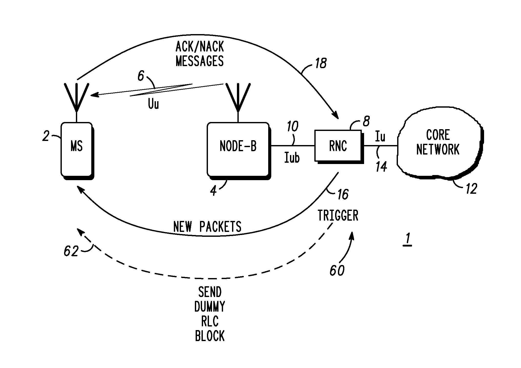
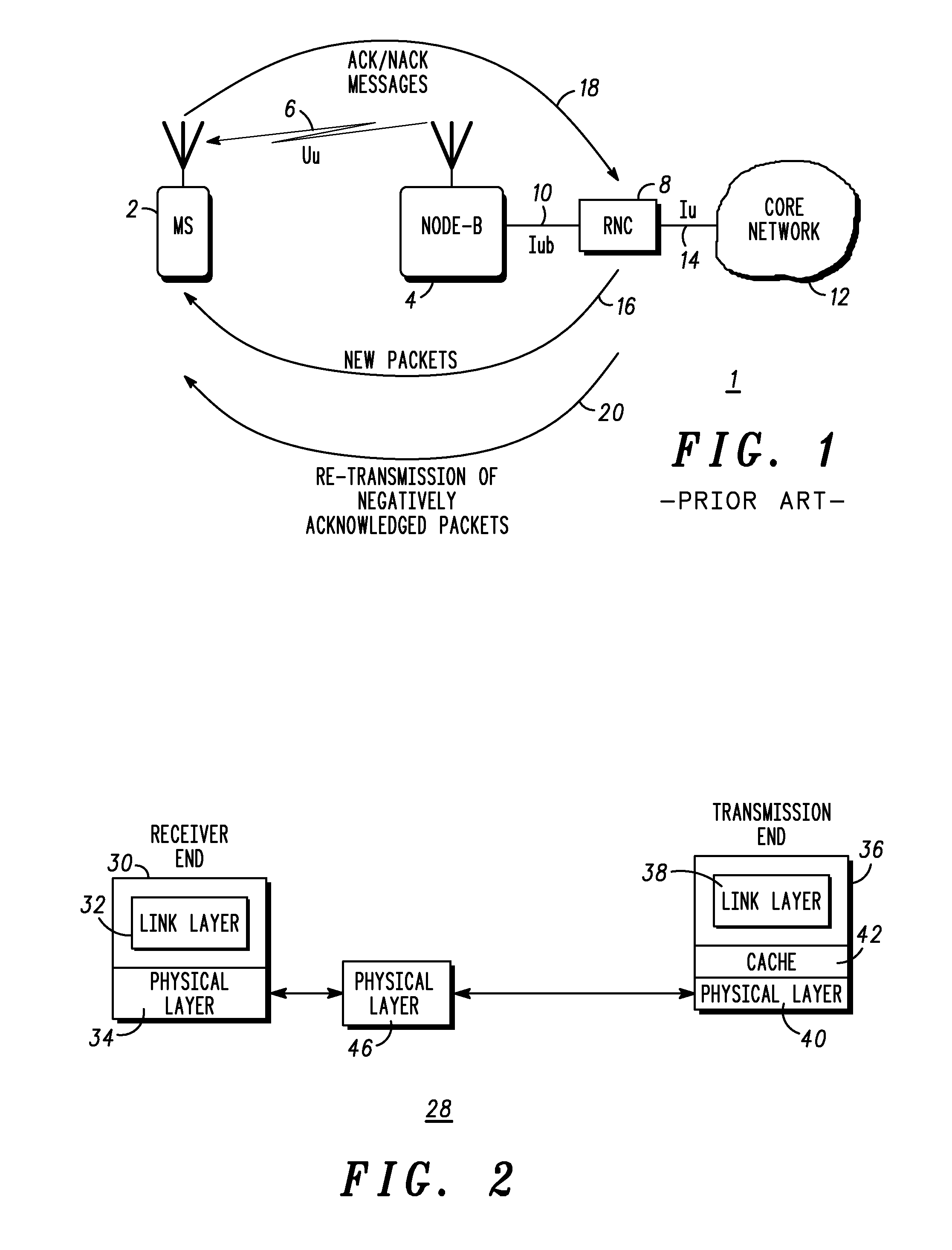
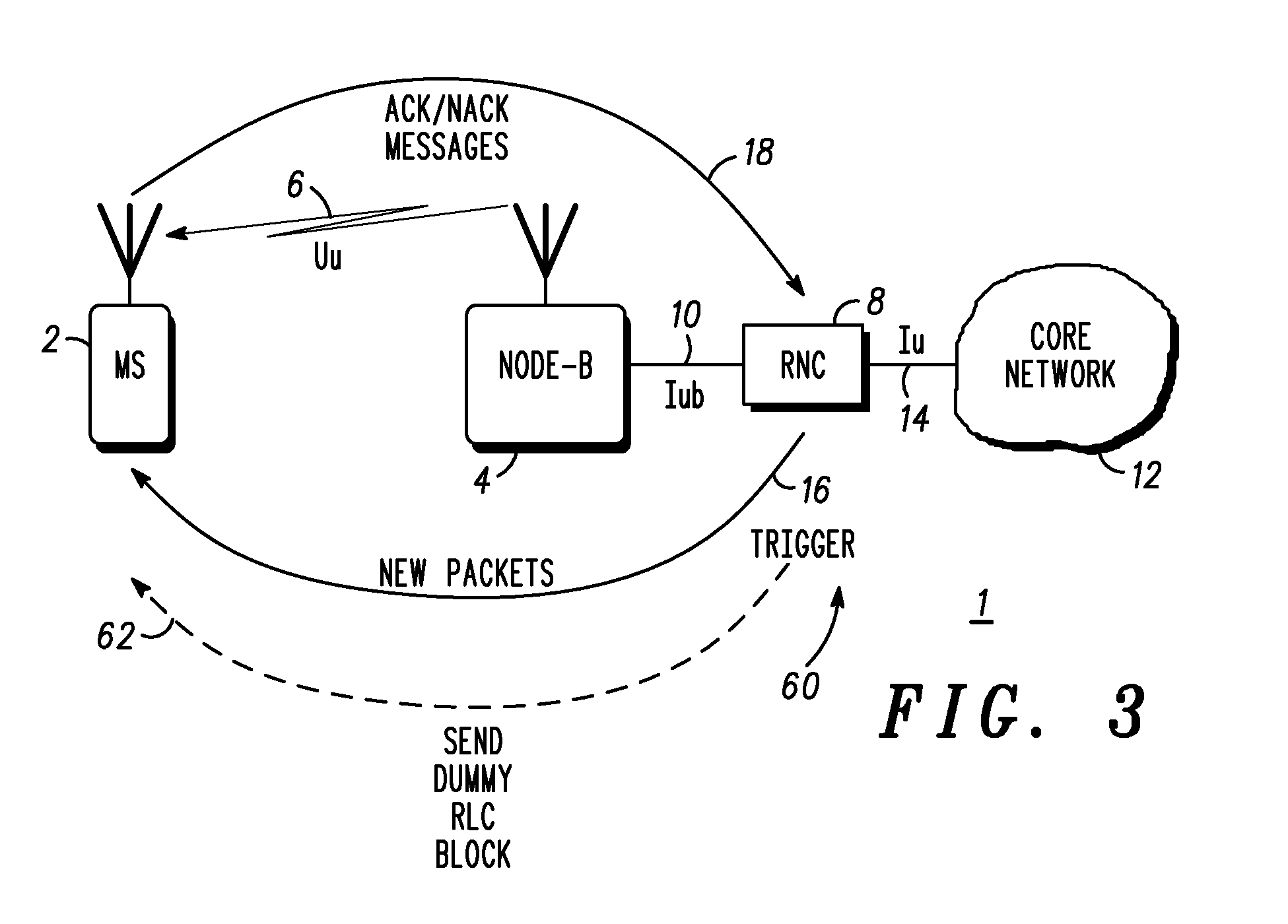
[0030]In general, this invention may be applied to a cellular communication system according to the Universal Mobile Telephone Standard (UMTS). The parts of such a communication system 1 which are helpful for understanding this embodiment are illustrated schematically in FIG. 1, for example. A user equipment such as mobile station (MS) 2, for use by an end-user, is coupled with a base transceiver station, known in UMTS as a Node-B, 4, via a radio link 6 operating according to the UMTS-specified Uu interface. The Node-B 4 is coupled to a Radio Network Controller (RNC) 8 via a physical link (e.g. a landlin...


PUM


Abstract

A packet data transmission protocol that uses transmission windows includes a packet control unit (PCU) (4, 8) that transmits (100) blocks of data packets from a first transmission window. A user equipment (UE) (2) sends (102) a negative acknowledgement to the PCU if the packets are not received properly, whereupon the PCU construct (106) a dummy radio link control (RLC) block (60), including at least header information upon event of an established (104) trigger (60) event. The PCU sends (108) the dummy RLC block at a more robust coding rate to prevent a RLC stall condition.

Description

FIELD OF THE INVENTION[0001]This invention relates to the transmission and retransmission of packet data, and in particular to a transmission protocol for packet data in a wireless communication system employing a transmission window.BACKGROUND OF THE INVENTION[0002]The transmission of data, in the form of data packets, across a digital communication network is typically performed using a mechanism known as a protocol stack. Protocols are used to organise the transmission of data by means of a hierarchy of protocol layers, the protocol layers being considered collectively as a protocol stack. The hierarchy of layers typically extends from a physical layer (which dictates the manner in which individual bits are transmitted), up through to an application layer, which determines, for example, how high-level computer programs interact with each other.[0003]One example of an intermediate layer of the protocol stack is a logical link control (LLC) layer, which controls the transmission of...

Claims


Application Information

Patent Timeline
29 Oct 2009
Publication
US20090268706A1
IPC
H04J3/00; H04W28/04
CPC
H04L1/0009; H04L1/187; H04L1/188; H04W28/04; H04L47/14; H04L47/38; H04L47/10; H04W28/02
Inventors
FEATHERSTONE, WALTER; CHEUNG, COLLEEN