Multicarrier modulation scheme as well as transmission apparatus and reception apparatus using the scheme

a multi-carrier modulation and receiver technology, applied in electromagnetic wave modulation, baseband system details, pulse technique, etc., can solve the problems affecting the effect of interfering signals, and limiting the carrier influenced by interfering signals, etc., to achieve the effect of reducing transmission power

Active Publication Date: 2009-10-29
INTERDIGITAL PATENT HLDG INC
View PDF9 Cites 50 Cited by
  • Summary
  • Abstract
  • Description
  • Claims
  • Application Information

AI Technical Summary

Benefits of technology

[0093]In the multicarrier modulation according to the present invention, it is possible to insert a predetermined known pilot signal without calculating an interference to a pilot signal from a data transmission signal at the transmission end. Further

Problems solved by technology

In a wireless mobile communication, a multipath propagation often causes a problem.
On the other hand, in the wire communication such as xDSL and power line communication, an interfering signal received from another system and/or device often causes a problem.
Therefore, in the OFDM/QAM, a carrier influenced by the interfering signal can be limited.
However, the guard interval for the OFDM/QAM is used only for absorbing the influence of the multipath, and is not used for transmitting effective information.
Therefore, as described in Patent Document 1, the OFDM/QAM has a problem that an efficiency with which a spectrum is used is low, and an

Method used


Image

  • Multicarrier modulation scheme as well as transmission apparatus and reception apparatus using the scheme
  • Multicarrier modulation scheme as well as transmission apparatus and reception apparatus using the scheme
  • Multicarrier modulation scheme as well as transmission apparatus and reception apparatus using the scheme

Examples


embodiment 1

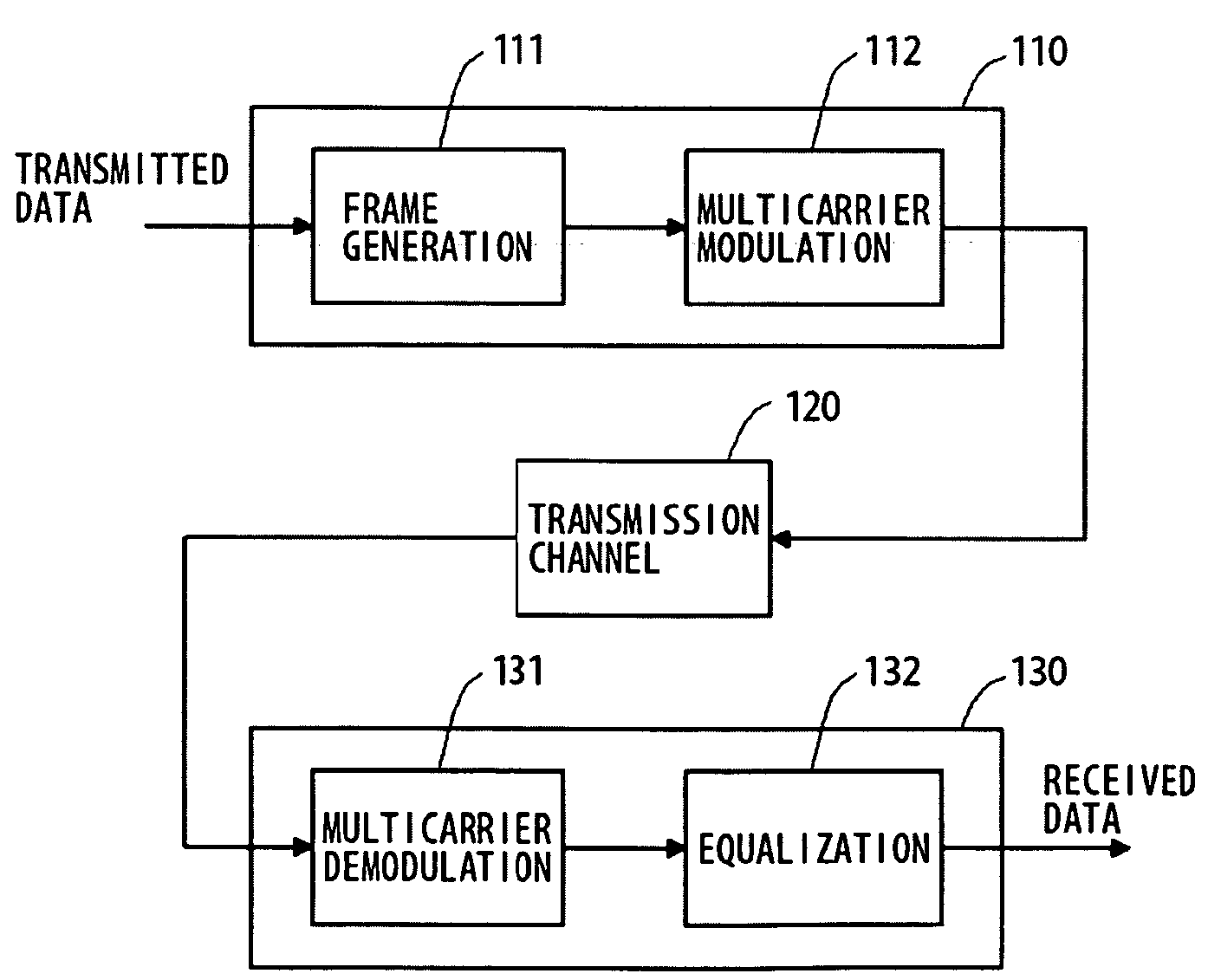
[0126]FIG. 1 is a diagram illustrating a clipped part of a frame format, represented on a time-frequency coordinate plane, for a multicarrier modulation scheme according to an embodiment 1 of the present invention. In FIG. 1, the abscissa axis represents symbols located in the time direction, and the ordinate axis represents carriers located in the frequency direction. A number on the abscissa axis represents a symbol number in the time direction whereas a number on the ordinate axis represents a carrier number in the frequency direction. A phase reference pilot signal 20 is located on the k-th carrier in the m-th symbol, and transmitted. An amplitude reference pilot signal 21 is located on the k-th carrier in the (m+1)th symbol, and transmitted. Data transmission signals 22 to 31 are located in the vicinity of the phase reference pilot signal 20 and the amplitude reference pilot signal 21, and transmitted. The data transmission signals 22 to 24 are located on the (k−1)th to the (k+...

embodiment 2

[0155]FIG. 5 is a diagram illustrating a clipped part of a frame format, represented on a time-frequency coordinate plane, for a multicarrier modulation scheme according to an embodiment 2 of the present invention. In FIG. 5, the abscissa axis represents symbols located in the time direction, and the ordinate axis represents carriers located in the frequency direction. A number on the abscissa axis represents a symbol number in the time direction whereas a number on the ordinate axis represents a carrier number in the frequency direction. A mark ◯ represents a phase reference pilot signal, a mark  represents an amplitude reference pilot signal, and a mark X represents a data transmission signal. In the embodiment 2, as shown in FIG. 5, the phase reference pilot signal and the amplitude reference pilot signal are located alternately every other symbol on the k-th carrier in the time direction, and transmitted.

[0156]The modulation amplitude of the phase reference pilot signal is supp...

embodiment 3

[0161]FIG. 6 is a diagram illustrating a clipped part of a frame format, represented on a time-frequency coordinate plane, for a multicarrier modulation scheme according to an embodiment 3 of the present invention. In FIG. 6, the abscissa axis represents symbols located in the time direction, and the ordinate axis represents carriers located in the frequency direction. A number on the abscissa axis represents a symbol number in the time direction whereas a number on the ordinate axis represents a carrier number in the frequency direction. A mark ◯ represents a phase reference pilot signal, and a mark X represents a data transmission signal. In the embodiment 3, as shown in FIG. 6, the phase reference pilot signals are located on the k-th carrier in the time direction and are continuously transmitted.

[0162]The modulation amplitude of the phase reference pilot signal is suppressed to zero at the transmission end. That is, the phase reference pilot signal is a null signal. Further, the...


PUM


Abstract

An object is to generate a pilot signal for estimating transmission characteristic of a transmission channel which is suitable for the OFDM/OQAM multicarrier modulation. A phase reference pilot symbol of which a modulation amplitude is suppressed to zero, and an amplitude reference pilot signal obtained through modulation performed by using an amplitude known to a reception end are transmitted from a transmission end, and the transmission characteristic of the transmission channel is estimated and compensated by using the phase reference pilot signal and the amplitude reference pilot signal at the reception end. Thus, it is possible to simplify frame generation process performed at the transmission end, and reduce transmission power for the phase reference pilot signal.

Description

TECHNICAL FIELD[0001]The present invention relates to a multicarrier modulation scheme capable of estimating transmission characteristic of a transmission channel by using a pilot signal as well as a transmission apparatus and a reception apparatus using the scheme, and more particularly, to a multicarrier modulation scheme capable of performing the aforementioned estimation in a suitable manner when OFDM / OQAM (Offset Quadrature Amplitude Modulation) multicarrier modulation is used, and a transmission apparatus and a reception apparatus using the scheme.BACKGROUND ART[0002]Multicarrier modulation is widespread for radio communication or wire communication. The multicarrier modulation is a scheme in which transmission data is divided, and the divided transmission data are assigned to a plurality of carriers, respectively, and the carriers corresponding to the respective transmission data are modulated, and the modulated carriers are multiplexed. The multicarrier modulation called OFD...

Claims


Application Information

Patent Timeline
IPC IPC(8): H04B7/02
CPCH04L5/0007H04L5/0048H04L25/0226H04L25/0228H04L2025/03414H04L27/2698H04L25/022H04L27/2647
Inventor KIMURA, TOMOHIROOMOTO, YUKIHIROMORI, KENICHI
Owner INTERDIGITAL PATENT HLDG INC
Why Eureka
Try Eureka