
Alignment Structure for a Wood Flat Drill Bit

a flat drill bit and alignment structure technology, which is applied in the direction of wood boring tools, manufacturing tools, transportation and packaging, etc., can solve the problems of inconvenient replacement of drill bits, inability to extend the length of flat drill bits, and inability to adjust the capability of hole drilling depth of wood flat drill bits

Inactive Publication Date: 2009-10-29
WANG EUPIN
View PDF0 Cites 21 Cited by
  • Summary
  • Abstract
  • Description
  • Claims
  • Application Information

AI Technical Summary

Benefits of technology

The present invention provides an alignment structure for a wood flat drill bit that allows it to be automatically aligned after assembly to a power tool. This is achieved through a connecting assembly and flat drill bit with conical portions that abut against each other, allowing for easy and quick replacement of the drill bit. The connecting assembly can be extended and shortened to drill different depth or sized holes. Overall, the invention provides a convenient and efficient solution for aligning and replacing wood flat drill bits.

Problems solved by technology

However, not any metalworking drill bit except those specially designed for woodworking can be used to process wood due to the special grain arrangement of the wood, especially in a hole drilling operation, a wood flat drill bit must be used.
First, such a wood flat drill bit can only drill one size of hole, and it should use another drill bit if another size hole needs to be drilled, thus causing inconvenience in replacing the drill bit.
Second, when other types of drill bits (such as screwdriver bit, grinding tools) need to be used, it will also cause inconveniences since it has to remove the wood drill bit from the power tool and assemble the desired bit on it).
Third, the conventional wood flat drill bit is usually long in order to drill different depth holes, however, in addition to the disadvantages of occupying a relatively large space and being inconvenient to use due to its relatively long length, such a wood flat drill bit cannot be extended in length because it is a integrally formed structure, in other words, such a conventional wood flat drill bit is not adjustable in hole drilling depth capability.
Fourth, the excessive long length makes the conventional wood flat drill bit more susceptible to vibration during hole drilling operation, further, the wood flat drill bit must be aligned properly when being assembled to or removed from a power tool, and the alignment operation is very time consuming.

Method used


Image

  • Alignment Structure for a Wood Flat Drill Bit
  • Alignment Structure for a Wood Flat Drill Bit
  • Alignment Structure for a Wood Flat Drill Bit

Examples


Embodiment Construction

[0021]The present invention will be clearer from the following description when viewed together with the accompanying drawings, which show, for purpose of illustrations only, the preferred embodiment in accordance with the present invention.

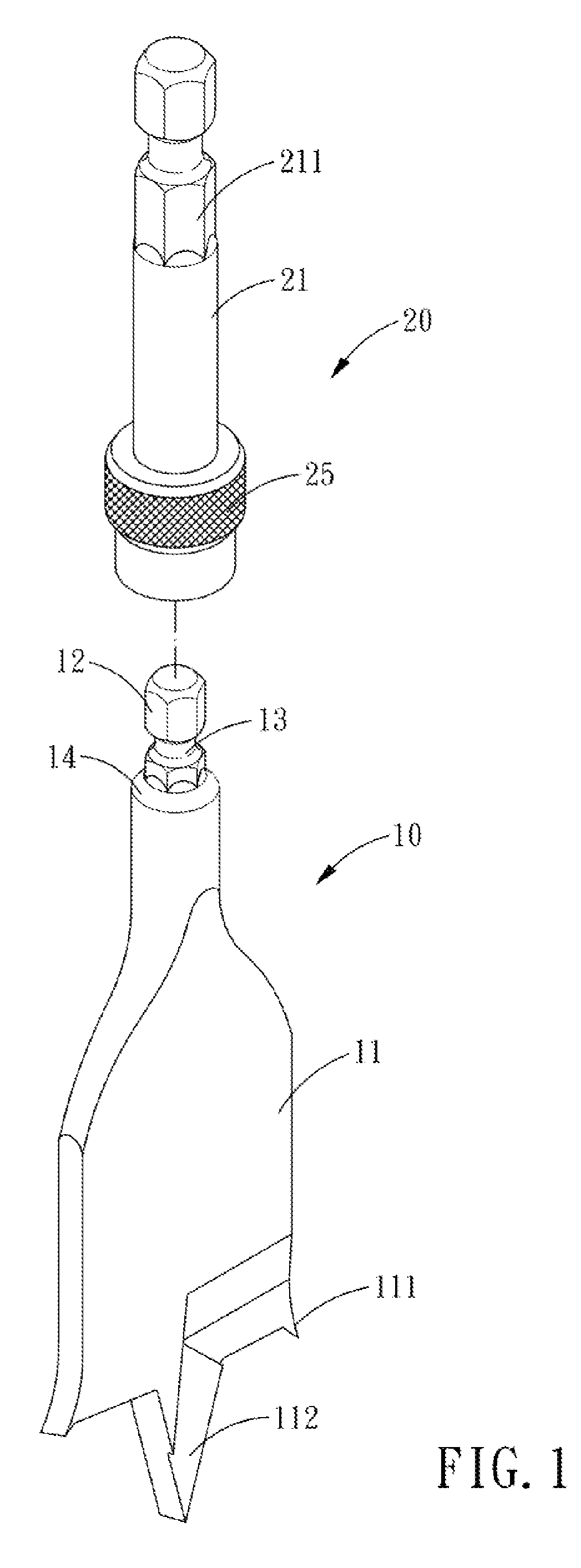
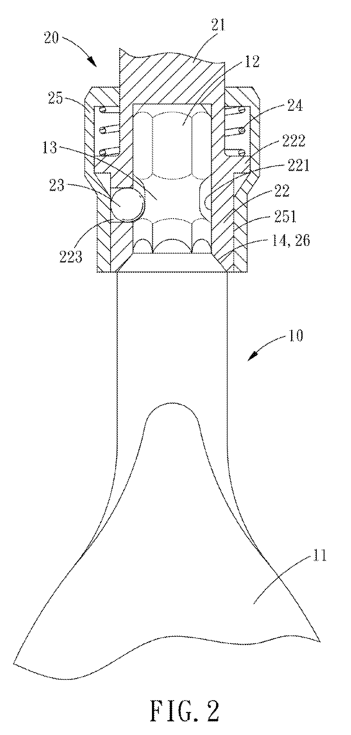
[0022]Referring to FIGS. 1-3, an alignment structure for a wood flat drill bit in accordance with the present invention is to be driven to rotate by a power tool and comprises: a flat drill bit 10 and a connecting assembly 20.

[0023]The flat drill bit 10 is a unitary structure having a flat drilling end 11 and an angular end 12. The flat drilling end 11 has two protruding cutting edge at both sides thereof and a central guiding edge 112. The angular end 12 is hexagonal in cross section, in the middle of the angular end 12 is defined an annular groove 13, and between the flat drilling end 11 and the angular end 12 is defined an outwardly slanted conical portion 14.

[0024]The connecting assembly 20 includes a connecting rod 21, a seat 22, a steel bal...


PUM

PropertyMeasurementUnit
alignment structureaaaaaaaaaa
structureaaaaaaaaaa
sizeaaaaaaaaaa

Abstract

An alignment structure for a wood flat drill bit comprises a flat drill bit and a connecting assembly. The drill bit has a flat drilling end and the other end of the drill bit is provided for positioning the connecting assembly. The connecting assembly and the flat drill bit are formed with conical portions for abutting against each other. Hence, the flat drill bit can be automatically aligned by abutting the conical portion of the flat drill bit against that of the connecting assembly.

Description

BACKGROUND OF THE INVENTION[0001]1. Field of the Invention[0002]The present invention relates to an alignment structure for a wood flat drill bit, and more particularly to a wood flat drill bit which is quickly replaceable and can be automatically aligned.[0003]2. Description of the Prior Art[0004]Conventionally, woods should be subjected to scraping, smoothing, sawing, chiseling, drilling and the like processes first, and then are assembled to form a desired structure. However, not any metalworking drill bit except those specially designed for woodworking can be used to process wood due to the special grain arrangement of the wood, especially in a hole drilling operation, a wood flat drill bit must be used. The working flat chisel has a cutting portion and a central cuspidal guiding portion formed in the front end thereof. At both ends of the cutting portion are formed a cone-shaped sharp edge for cutting the wood grain, and the cuspidal guiding portion in the center of the frond e...

Claims


Application Information

Patent Timeline
Patent Type & Authority Applications(United States)
IPC IPC(8): B23B51/00
CPCB23B31/008B23B31/1071Y10T408/899B27G15/00B23B31/11
Inventor WANG, EUPIN
Owner WANG EUPIN
Learn More