Bone Plate System

a technology of bone plate and plate plate, applied in the field of bone plate system, can solve the problems of tearing soft tissues supporting the spine, breaking bones, and deteriorating bones

a technology of bone plate and plate plate, applied in the field of bone plate system, can solve the problems of tearing soft tissues supporting the spine, breaking bones, and deteriorating bones

US20090270927A1Active Publication Date: 2009-10-29PIONEER SURGICAL TECH INC

Image

  • Bone Plate System
  • Bone Plate System
  • Bone Plate System

Examples


Embodiment Construction

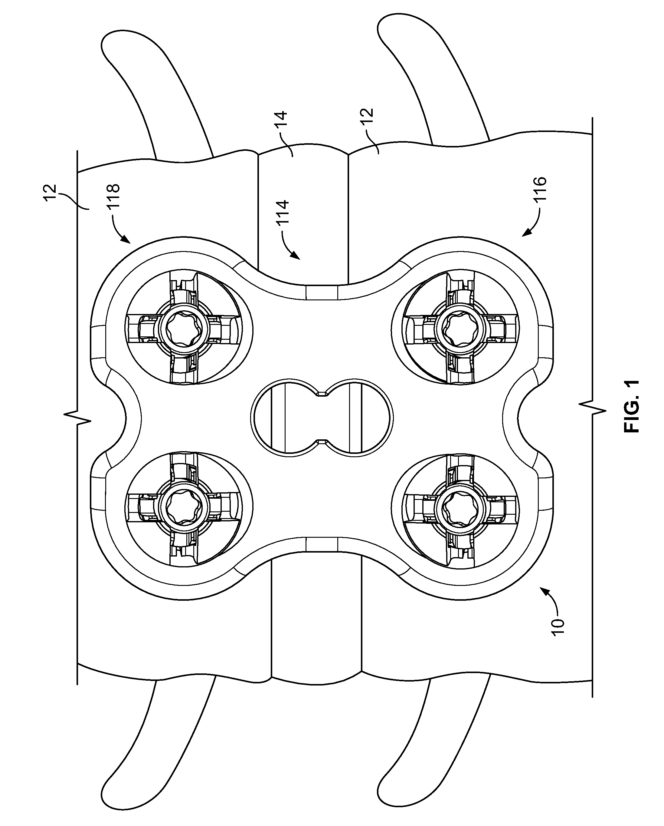
[0079]Referring initially to FIG. 1, a bone plate system 10 is depicted shown connected on the anterior surface of adjacent lumbar vertebrae 12 that are spaced by an intervertebral disc 14. In general, the bone plate system 10 may be used to secure one or more bones in a desired spatial relationship to aid in their healing. The bone plate system 10 may also be used to assist in the healing necessary after trauma or degenerative disorders have affected the intervertebral disc 14. Furthermore, the bone plate system 10 may be used to correct and / or relieve a variety of spinal disorders, including but not limited to degenerative disorders, disorders induced by trauma, and pinched nerves.

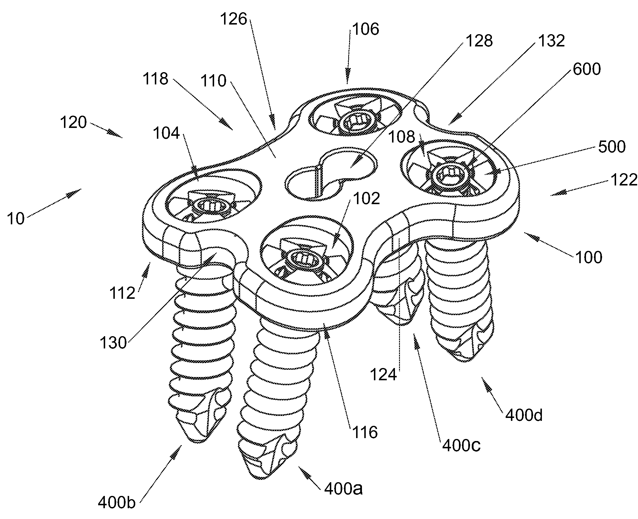
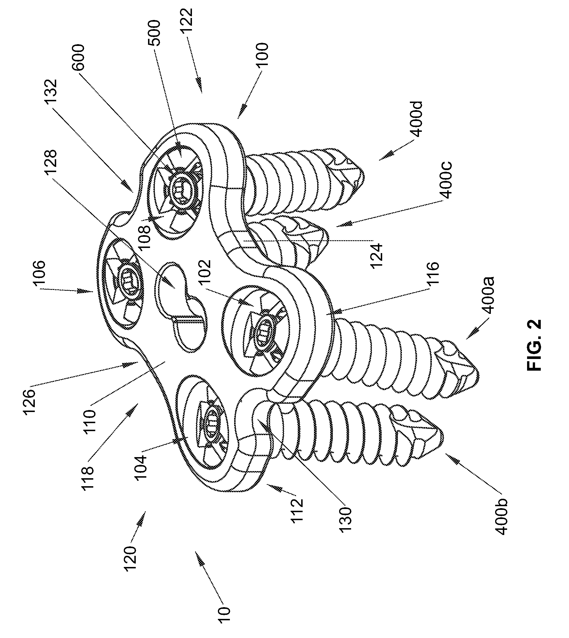
[0080]Turning to FIG. 2, the bone plate system 10 is shown having a bone plate 100 and bone anchor assemblies 400a-400d. The bone plate 100 is generally configured to be placed on one or more bones before bone anchor assemblies 400 are inserted into through bores 102, 104, 106, 108 which extend between u...


PUM


Abstract

A bone plate system is provided that includes bone plates and bone anchor assemblies for being inserted into bone plate bores to secure the bone plates to one or more bones. In one aspect, the bone plate system includes a bone anchor assembly having a locking cap and a locking fastener connected to a head portion of a bone anchor. The bone anchor assembly is driven into a bone plate bore before the locking fastener is shifted to expand the locking cap and fix the bone anchor assembly within the bore. In another aspect, the bone plate system includes a bone anchor assembly having a locking cap that deflects radially inward due to contact with the bone plate at large bone anchor assembly insertion angles. In addition, a bone anchor assembly having a preassembled condition with a locking cap resisting back out of a locking fastener.

Description

CROSS-REFERENCE TO RELATED APPLICATIONS[0001]This application claims the benefit of U.S. Provisional Application Ser. No. 61 / 047,926, filed Apr. 25, 2008, which is hereby incorporated by reference as if fully set forth herein.FIELD OF THE INVENTION[0002]The invention relates to a bone plate system and, more particularly, to a bone plate system that allows for polyaxial bone anchor insertion and rigid fixation of the bone anchor relative to a bone plate.BACKGROUND OF THE INVENTION[0003]There are presently many different types of plate and fixture systems for securing two or more bones or bone fragments in relative position so that the bones may fuse or heal, or so that tissue adjacent the bones may heal without disruption from the movement of the secured bones. As used herein, the term bone may refer to a bone, or a bone fragment or portion, and the term may refer to a portion of a bone that is covered with another material, such as the endplates covering the top and bottom surface o...

Claims


Application Information

Patent Timeline
29 Oct 2009
Publication
US20090270927A1
IPC
A61B17/80; A61B17/86
CPC
A61B17/7059; A61B17/8047; A61B17/8038
Inventors
PERROW, SCOTT J.; FREDIN, BRAD