Drive health monitoring with provisions for drive probation state and drive copy rebuild

a technology of health monitoring and provisioning, applied in the direction of redundant data error correction, fault response, instruments, etc., can solve the problems of array controllers not being able to recover, drive reliability problems on one or more drives, and potential for data corruption

Active Publication Date: 2009-10-29
AVAGO TECH INT SALES PTE LTD
View PDF22 Cites 34 Cited by
  • Summary
  • Abstract
  • Description
  • Claims
  • Application Information

AI Technical Summary

Problems solved by technology

However an array controller's ability to recover from such drive exceptions may result in the development of drive reliability problems on one or more drives in a RAID group over an extended period of time.
Also the potential for data corruption may increase as drive reliability problems develop on any of the drives in a RAID group.
As such, by the time a first drive is failed by the array controller, the remaining drives in the RAID group may also develop reliability problems that the array controller can no longer recover from following a loss of redundant data.
Such a scenario often results in the loss of data availability because of a failure of a second drive during the rebuild process for the first failed drive.
The potential for this loss of data availability may be even greater when larger or less expensive drives are used in a RAID group.
Even when a sufficient number of reliable drives remain to rebuild data on a failed drive or drives, the rebuild process may be time consuming requiring special hardware and complex reconstruction software procedures.
The time it takes to completely rebuild the data from a first drive on a replacement drive increases the potential for a subsequent drive failure on a second drive that will result in a loss of data availability.
There may also be a potential for the replacement drive for the first drive to fail during the rebuild process further threatening data availability by expanding the window of opportunity for second drive failure.
However, SMART may be inadequate at detecting drives with developing reliability problems.
An array controller may fail a drive because a required IO command could not be completed or because the drive may be exhibiting degraded performance but at no time does the drive report a SMART error.
However, the media scan may be incapable of keeping up with the creation of new media errors.
The external analysis of array and drive exception logs cannot provide rapid detection of an unreliable drive because of the inherent delay of the polling cycle and overhead of the error log analysis.
The technique can also impact performance and increase total storage cost especially if the function may be performed by a separate service processor.
However, the external analysis of array and drive exception logs cannot provide rapid detection of an unreliable drive because of the inherent delay of the polling cycle and overhead of the error log analysis.
The technique can also impact performance and increase total storage cost especially if the function may be performed by a separate service processor.
Use of a fewer number of drives in each RAID group reduces the potential for multiple drive failures and subsequent loss of data availability.
However, use of a RAID configuration with additional data redundancy, such as RAID-6, impacts performance and requires additional drives which increases total storage cost.
Conversely, restricting the number of drives in a RAID group, as a means to improve reliability, increases total storage cost while storage market requirements push for larger number of drives in a RAID group in order to reduce cost.
Other alternatives that limit the drive IO workload or use more reliable drives increase total storage cost.
Some ways to reduce the drive IO workload may be using a larger array controller cache or artificially limiting the array performance.
However, these mechanisms may increases storage cost or the time to rebuild a failed drive on the replacement drive increases.

Method used


Image

  • Drive health monitoring with provisions for drive probation state and drive copy rebuild
  • Drive health monitoring with provisions for drive probation state and drive copy rebuild
  • Drive health monitoring with provisions for drive probation state and drive copy rebuild

Examples


Embodiment Construction

[0021]In the following detailed description, reference is made to the accompanying drawings, which form a part hereof. In the drawings, similar symbols typically identify similar components, unless context dictates otherwise. The illustrative embodiments described in the detailed description, drawings, and claims are not meant to be limiting. Other embodiments may be utilized, and other changes may be made, without departing from the spirit or scope of the subject matter presented here.

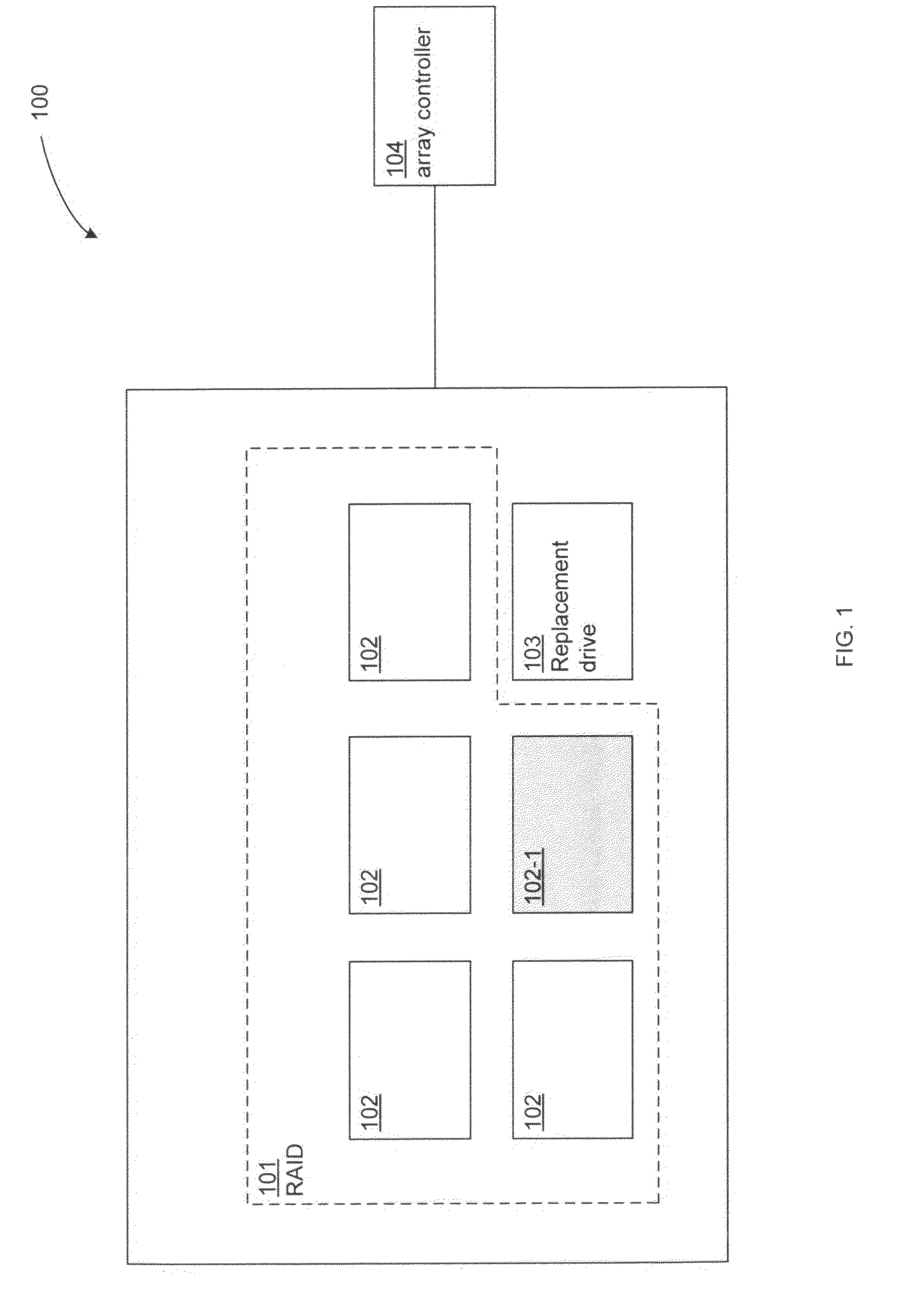
[0022]FIG. 1 illustrates an example system 100 in which one or more technologies may be implemented. The system 100 may comprise a redundant array of independent drives (RAID) 101 including drives 102, a non-RAID replacement drive 103, and an array controller 104.

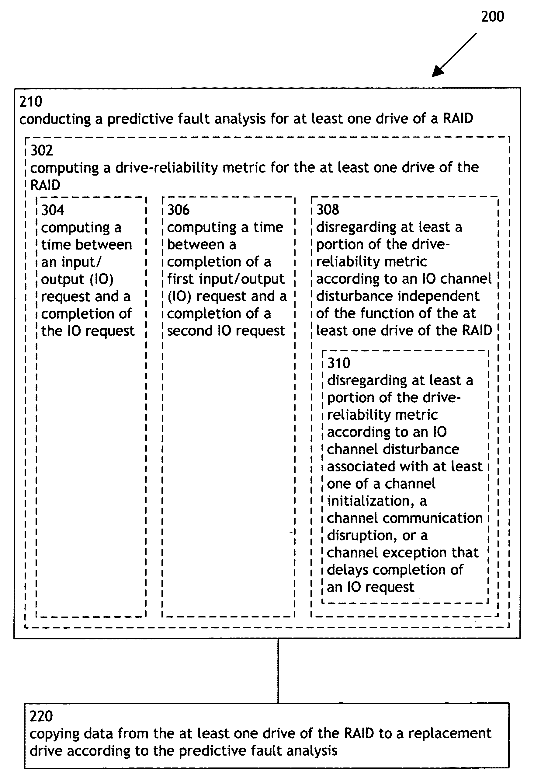
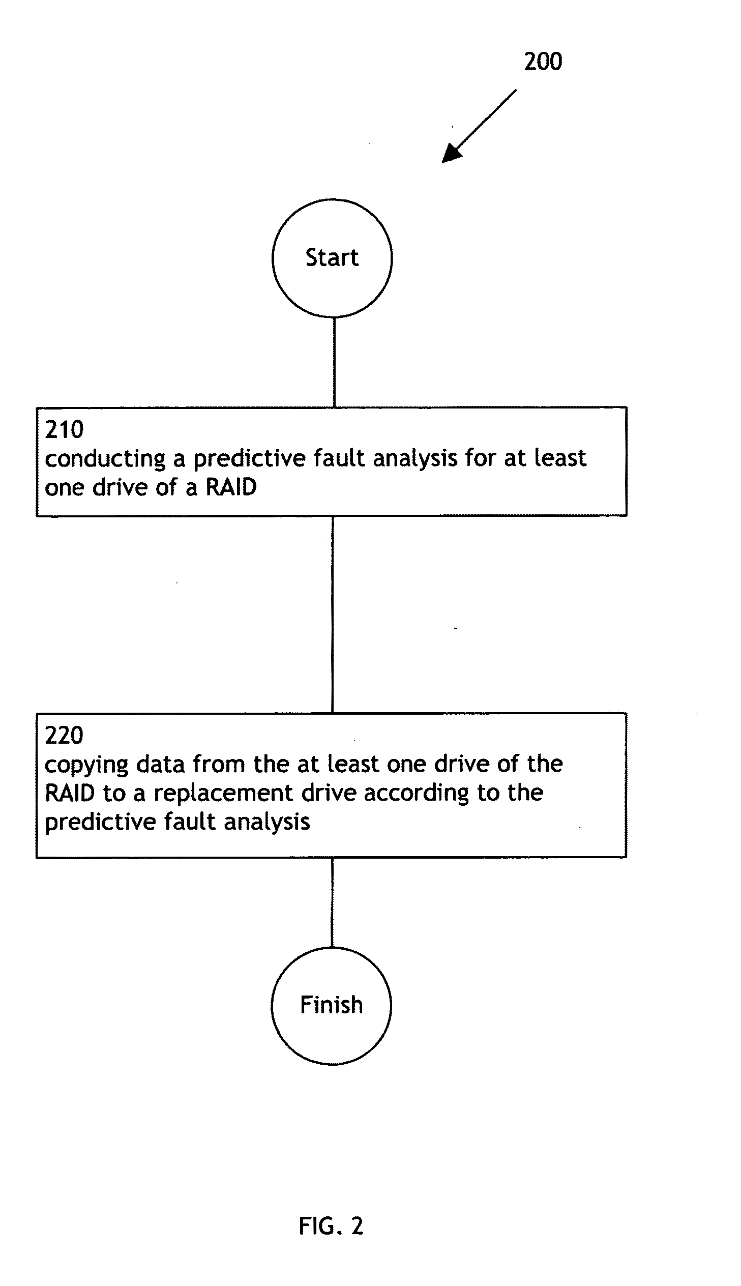
[0023]FIG. 2 illustrates an operational flow 200 representing example operations related to drive health monitoring. In FIG. 2 and in following figures that include various examples of operational flows, discussion and explanation may be prov...


PUM


Abstract

The present disclosure is directed to a system and method for monitoring drive health.
A method for monitoring drive health may comprise: a) conducting a predictive fault analysis for at least one drive of a RAID; and b) copying data from the at least one drive of the RAID to a replacement drive according to the predictive fault analysis.
A system for monitoring drive health may comprise: a) means for conducting a predictive fault analysis for at least one drive of a RAID; and b) means for copying data from the at least one drive of the RAID to a replacement drive according to the predictive fault analysis.

Description

BACKGROUND[0001]Array controllers employ mechanisms for recovering from drive media exceptions by utilizing the data redundancy inherent in most types of redundant array of independent disk (RAID) storage configurations. However an array controller's ability to recover from such drive exceptions may result in the development of drive reliability problems on one or more drives in a RAID group over an extended period of time. Also the potential for data corruption may increase as drive reliability problems develop on any of the drives in a RAID group. As such, by the time a first drive is failed by the array controller, the remaining drives in the RAID group may also develop reliability problems that the array controller can no longer recover from following a loss of redundant data. Such a scenario often results in the loss of data availability because of a failure of a second drive during the rebuild process for the first failed drive.[0002]The potential for this loss of data availab...

Claims


Application Information

Patent Timeline
Patent Type & Authority Applications(United States)
IPC IPC(8): G06F11/20G06F12/00G06F12/16
CPCG06F11/004G06F11/1662G06F2201/81G06F11/3419G06F11/3485G06F11/2094
Inventor MCCOMBS, CRAIG C.NAIR, NAMANJESS, MARTINBIRZER, JEREMY
Owner AVAGO TECH INT SALES PTE LTD
Why Eureka
Try Eureka