Remote Control System for Remotely Controlling an Electronic Card Connected to a Television Screen or Monitor and Associated Method for Transmitting Control Signals

a technology of remote control and electronic card, which is applied in the field of remote control system, can solve the problems that the perception of the use of the remote control remains complex for the average user, and achieve the effect of not hiding the broadcast imag

Inactive Publication Date: 2009-11-05
WYPLAY
View PDF3 Cites 8 Cited by
  • Summary
  • Abstract
  • Description
  • Claims
  • Application Information

AI Technical Summary

Benefits of technology

[0016]According to another embodiment of the invention, the zone of reduced size superimposed on the image of the screen, zone which contains the display of the keypad of the remote control system and of the position of the finger, is positioned in a corner of the screen in such a way as to not hide the broadcast image. As such, the user can see the image on the screen as well as said zone in a simple glance without obstruction.
[0017]According to another embodiment of the invention, the keypad further comprises at least one cursor provided with its system of detecting and of locating the finger of the user placed on this said cursor thus making possible the display on the screen of the cursor of the remote control system and of the position of the finger.

Problems solved by technology

However, in the majority of cases, only a few keys are required, approximately eight, rendering the forty and a few others little used.
Consequently, the perception of the use of the remote control remains complex for the average user who does not know the functionality of said keys.

Method used


Image

  • Remote Control System for Remotely Controlling an Electronic Card Connected to a Television Screen or Monitor and Associated Method for Transmitting Control Signals
  • Remote Control System for Remotely Controlling an Electronic Card Connected to a Television Screen or Monitor and Associated Method for Transmitting Control Signals
  • Remote Control System for Remotely Controlling an Electronic Card Connected to a Television Screen or Monitor and Associated Method for Transmitting Control Signals

Examples


Embodiment Construction

)

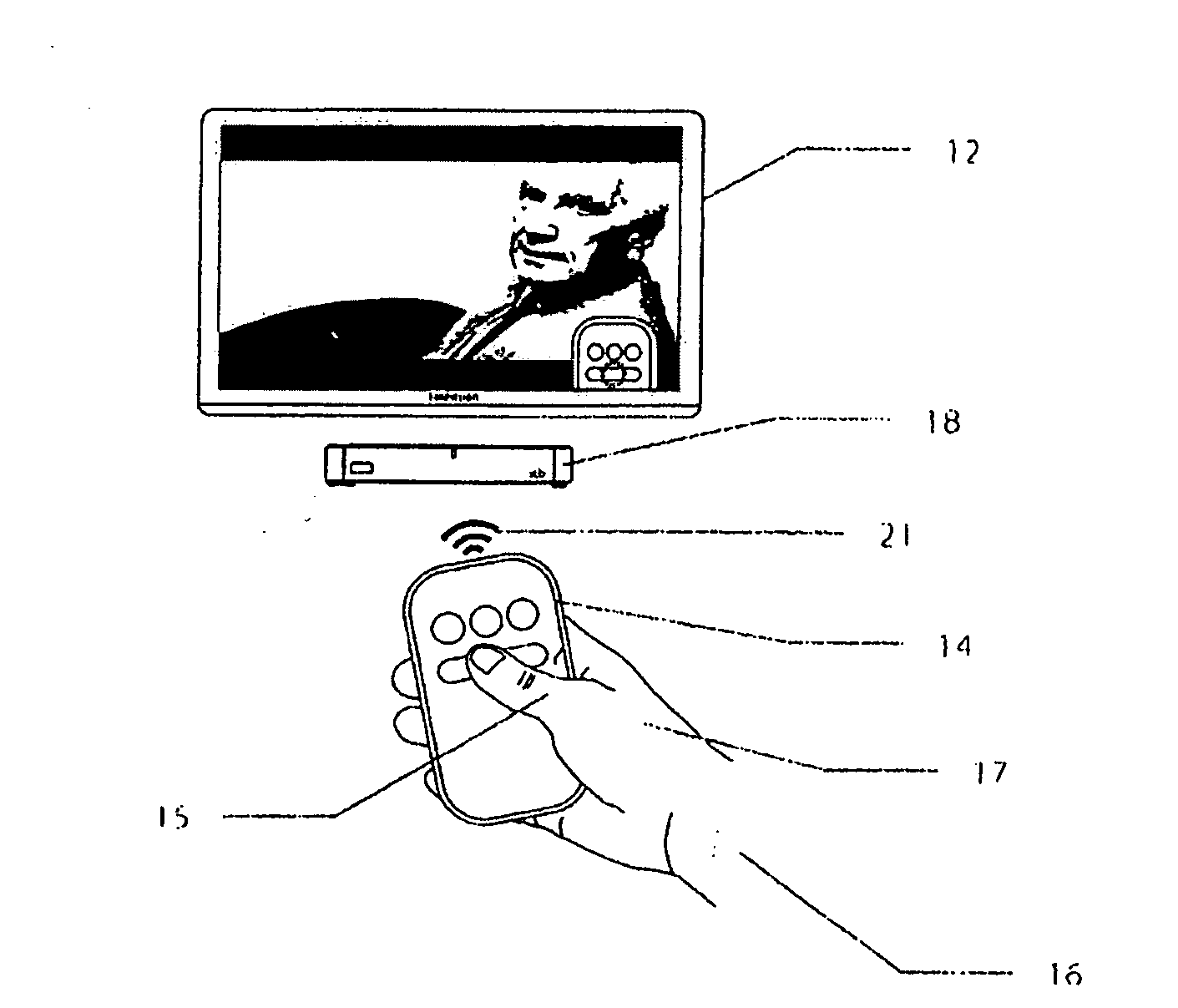
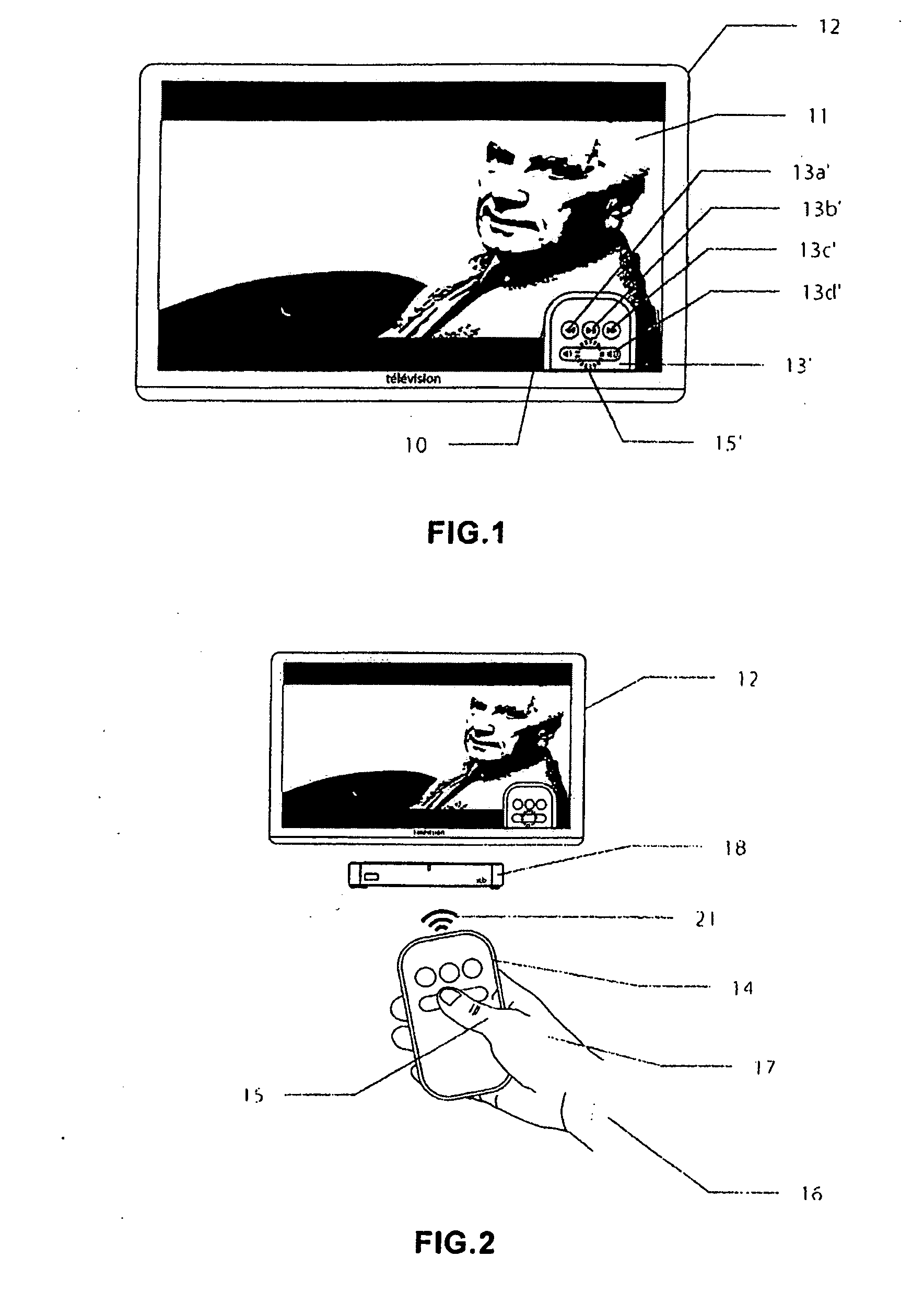
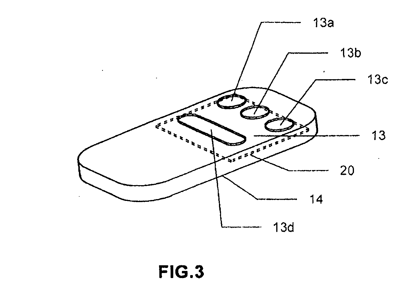
[0034]The objective of this invention is to display, according to FIG. 1 in a zone 10, superimposed on the image 11 of the television 12, the keypad 13 of the remote control 14 with the position in real time of the thumb 15 of the user 16 on the latter 13. This zone 10 is of small size, located more preferably in a corner of the image 11 of the television 12, in such a way as to not hide the image 11 of the television 12.

[0035]According to FIG. 2, the user 16 can therefore press on the remote control 14 that he has in his hand 17, without having to look at it, since the latter is displayed on the screen. This as such makes it possible:

[0036]always keep his eyes fixed on the television 12 (according to FIG. 1),

[0037]facilitate the use of the remote control 14 in a dark environment where it is very difficult to see the keys of the remote control 14 and their associated functions,

[0038]change the functions associated with the keys of the remote control 14 according to what is displaye...


PUM


Abstract

A remote control system is provided for remotely controlling, by the hand of a user, an electronic card connected to a screen (monitor or television). This remote control system includes at least: a keypad, an onboard processor and a system for transmitting signals intended for the electronic card. A method for reproducing the keypad of the remote control system on a zone of reduced size superimposed on the image of the screen is provided. The image of the keypad on the screen displays virtually, and in real time, the position of the thumb of the hand of the user placed on the remote control system. The image of the keypad on the screen, referred to as zone of reduced size, is more preferably located in a corner of the screen in such a way as to not hide the broadcast image. Finally, a method for transmitting control signals using a remote control system controlled by the hand of a user intended for an electronic card connected to a television screen or monitor is provided.

Description

BACKGROUND[0001](1) Field of the Invention[0002]This invention relates to:[0003]A remote control system for remotely controlling, by the hand of a user, an electronic card connected to a screen (monitor or television); this remote control system comprising at least one keypad, an onboard processor and a system for transmitting signals intended for said electronic card, and[0004]A method for reproducing the keypad of said remote control system on a zone of reduced size superimposed on the image of the screen; on this image of the keypad on the screen is displayed virtually, and in real time, the position of the finger of the hand of the user placed on the remote control system; this image of the keypad on the screen, called the zone of reduced size, is more preferably located in a corner of the screen in such a way as to not hide the broadcast image.[0005](2) Prior Art[0006]The remote controls of prior art have a keypad comprising a certain number of keys each corresponding to a func...

Claims


Application Information

Patent Timeline
Patent Type & Authority Applications(United States)
IPC IPC(8): H04N5/44H04N5/445
CPCH04N5/4403H04N5/44582H04N5/76H04N21/42228H04N2005/4441H04N21/42224H04N2005/443H04N21/42204H04N21/47
Inventor BARBAROUX, ALEXANDRELUCIANI, PAULBLANES, YORICKVIGNES, ROMAINMARCHET, MAXIMESERVIGNAT, DAVIDFERAL, DOMINIQUE
Owner WYPLAY
Why Eureka
Try Eureka